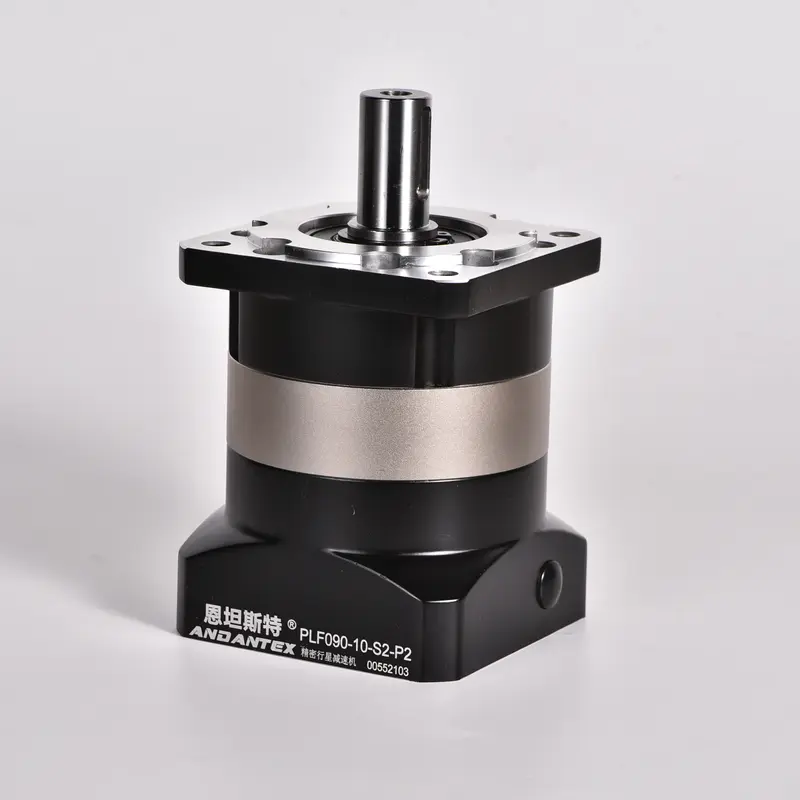
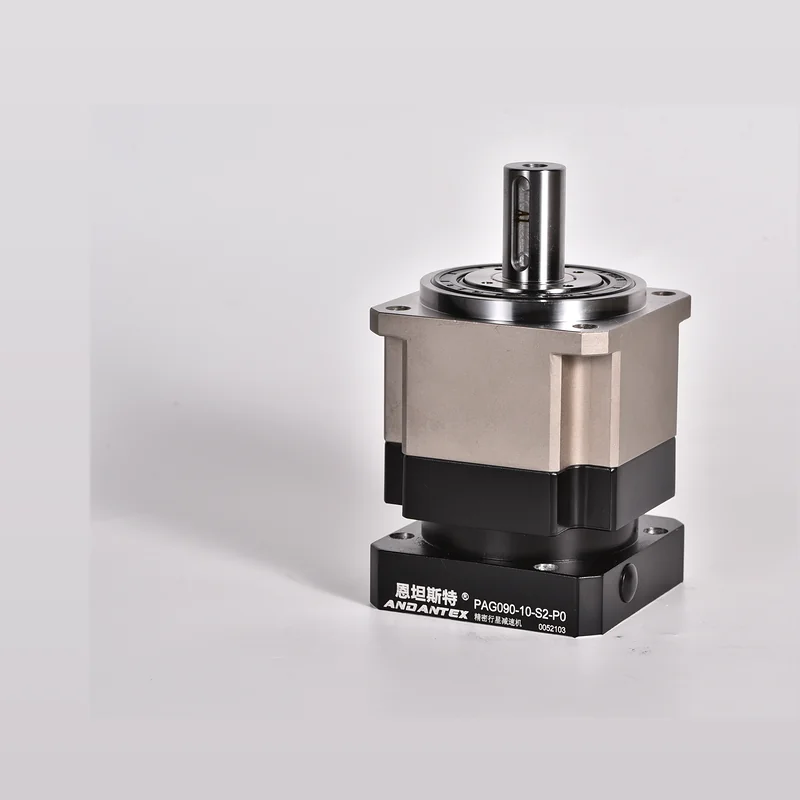
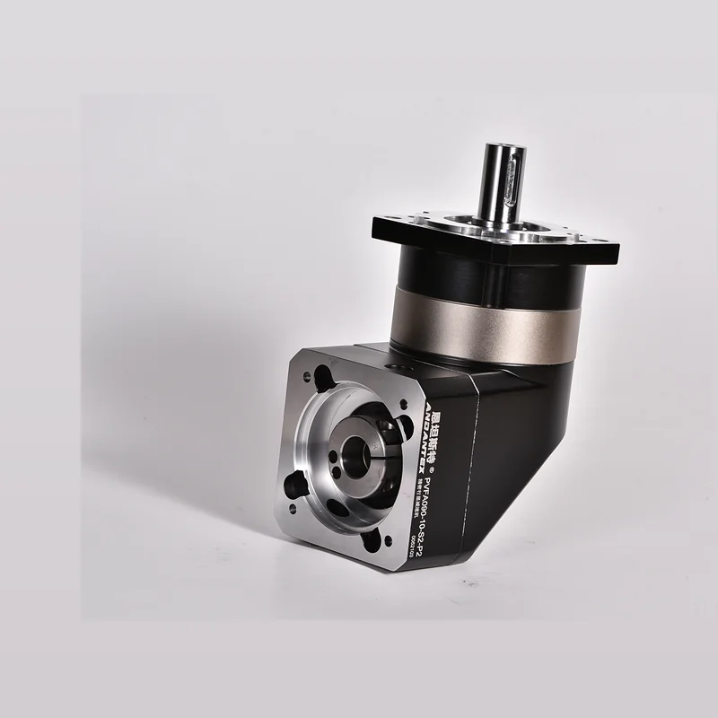
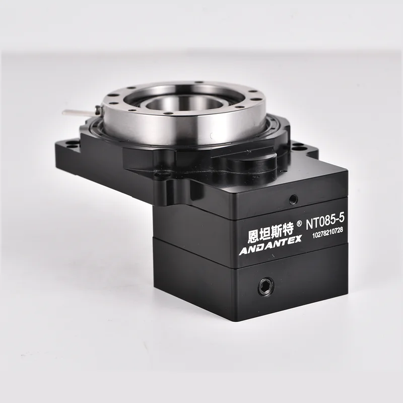
90 Frame Size · Square-Flange Helical · Low-Backlash Precision Type

Square-Flange Helical Planetary, Rated Output Torque 130 Nm, Backlash 3 arcmin, Suitable for Rigidity Requirements, Automation axes requiring low backlash and stable positioning.
Data from the current ANDANTEX Compiled from published official website pages, Managed using the updated field structure during migration.
| Item | Parameters | Description |
|---|---|---|
| Series / Frame Size | PAG / 90 | Square-Flange Helical |
| Example Gear Ratio | 5 | The series also offers 3/4/7/10 And two-stage ratios |
| Backlash | 3 arcmin | Low-Backlash Precision Applications |
| Rated Output Torque | 130 Nm | Verify continuous operation for the chosen ratio |
| Maximum Radial Force | 3250 N | Calculate using the load application point |
| Maximum Axial Force | 1300 N | Check carefully when thrust loads are present |
| Torsional Rigidity | 12 Nm/arcmin | Affects dynamic positioning and resistance to torsional deformation |
| Maximum Input Speed | 8000 rpm | Monitor temperature rise during continuous high-speed operation |
| Typical Interface | Shaft Diameter 19 / Pilot Diameter 70 / Hole Spacing 90 | Confirm against the actual motor drawing |
Calculate the gear ratio from the output speed first, Then check rated torque, Peak Torque, Inertia & Cycle Time.
Currently Listed 3 Verified Interface Groups, L1, L2 Each Has Matching 2D and STEP. Final orders must be verified against the motor drawing.
| Interface Code | Shaft Diameter | Locating Pilot | Mounting Hole Spacing | Typical Motor | Description | Status |
|---|---|---|---|---|---|---|
| 14-73-98.4 L1 / L2 |
14 mm | 73 mm | 98.4 mm | Confirm against Motor Drawings | 2D and STEP Complete | Verified |
| 19-70-90 L1 / L2 |
19 mm | 70 mm | 90 mm | 750W Common Servo Interfaces | 2D and STEP Complete | Verified |
| 19-80-100 L1 / L2 |
19 mm | 80 mm | 100 mm | 750W Common Servo Interfaces | 2D and STEP Complete | Verified |
Each interface configuration has one 2D Drawing and one 3D STEP; L1, L2 Managed Separately, Files Are Not Shared.
Must Be Confirmed Together L1 / L2, Shaft Diameter, Pilot Diameter & Mounting Hole Spacing; Single-stage versions of the same interface, Two-stage versions differ in overall length, Do Not Mix Configurations.
PAG The current published example is 3 arcmin, Suitable for Indexing, Inspection, Assembly & High-Repeatability Applications.
Radial/Higher axial load capacity and torsional rigidity, Suitable for axes requiring higher structural rigidity.
Input Power, Shaft Diameter, Pilot Diameter, Hole Spacing, Structure & Torque Requirements, The system provides candidate models first, An engineer then reviews the selection.
No. Also consider the output speed, Load Torque, Peak Torque, Inertia, Confirm acceleration/deceleration time and motor interface together.
At minimum, check shaft diameter, Shaft Length/Keyway, Pilot Diameter & Mounting Hole Spacing, Confirm threads and flange thickness when necessary.
Open the current resource page from the engineering resources section; For actual projects, confirm the final drawing version for the specific motor interface.
Combine the motor interface, Gear Ratio, Output torque and operating conditions in one specification sheet, Reduce repeated clarification.