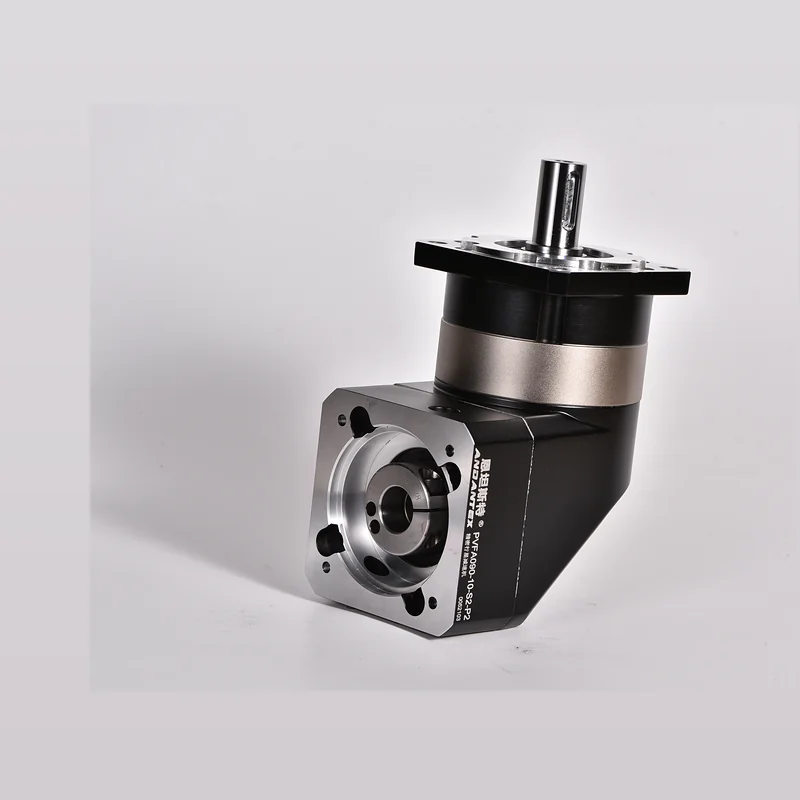
90 Frame Right-Angle Square-Flange Planetary Gearbox, Suitable for Space-Constrained Equipment, Requires 90°Automation mechanisms with right-angle output.

90 Frame Right-Angle Square-Flange Planetary Gearbox, Suitable for Space-Constrained Equipment, Requires 90°Automation mechanisms with right-angle output.
The following specifications are compiled from published website data, Final model-by-model verification by an engineer is recommended.
| Item | Parameters | Description |
|---|---|---|
| Example Model | PVFA090-5-S2-P2 | 90 Frame Right-Angle Square Flange |
| Gear Ratio | 3,4,5,7,10…100 | Published Series Range |
| Rated Output Torque | 122 Nm | Published Example Value |
| Backlash | 8 arcmin | Published Example Value |
| Maximum Radial Force | 450 N | Official Website Data |
| Maximum Axial Force | 430 N | Official Website Data |
| Maximum Input Speed | 6000 rpm | Official Website Data |
| Efficiency | 0.95 | Official Website Data |
Calculate the gear ratio from the output speed first, Then check rated torque, Peak Torque, Inertia & Cycle Time.
Currently Listed 4 Interface Groups, Including 4 Groups with Verified Examples. Final orders must be verified against the motor drawing.
| Interface Code | Shaft Diameter | Locating Pilot | Mounting Hole Spacing | Typical Motor | Description | Status |
|---|---|---|---|---|---|---|
| 19-70-90 L1 |
19 mm | 70 mm | 90 mm | 750W Common Servo Interfaces | Common Right-Angle Interfaces | Verified Example |
| 19-80-100 L2 |
19 mm | 80 mm | 100 mm | 750W Servo | Two-Stage Right-Angle Interface Example | Verified Example |
| 24-95-115 L1 |
24 mm | 95 mm | 115 mm | Large-Shaft Servo | Large-Shaft Interface Example | Verified Example |
| 22-110-145 L1 |
22 mm | 110 mm | 145 mm | Medium- & High-Power Servo | Overtorque / Custom Interface Example | Verified Example |
2D, 3D Motor interfaces are managed under the same product model, Different motor interfaces do not require duplicate product pages.
Input interfaces and dynamic operating conditions are easily overlooked. In addition to gear ratio and rated torque, Check motor shaft dimensions as well, Pilot Diameter, Hole Spacing, Acceleration & Deceleration Time, Inertia & Offset Loads.
Confirm the shaft diameter against the motor drawing, Shaft Length, Pilot Diameter, Key dimensions including mounting hole spacing, Then determine the input flange and bushing configuration.
Combine the motor interface, Gear Ratio, Output torque and operating conditions in one specification sheet, Reduce repeated clarification.