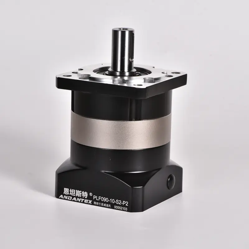
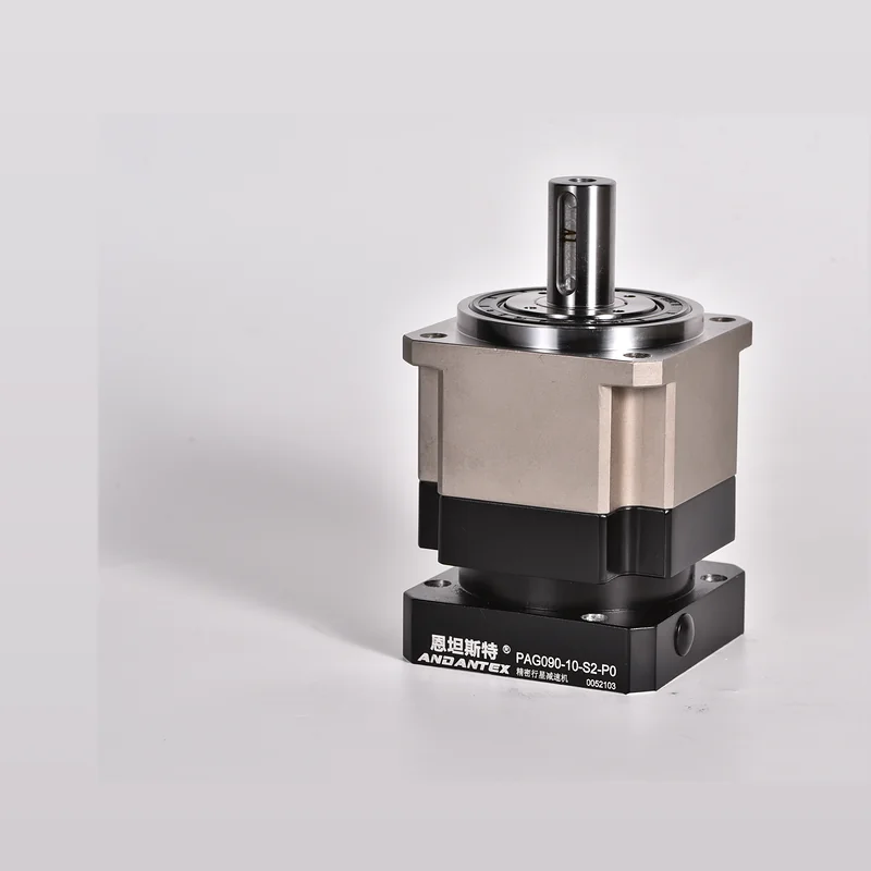
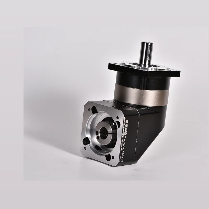
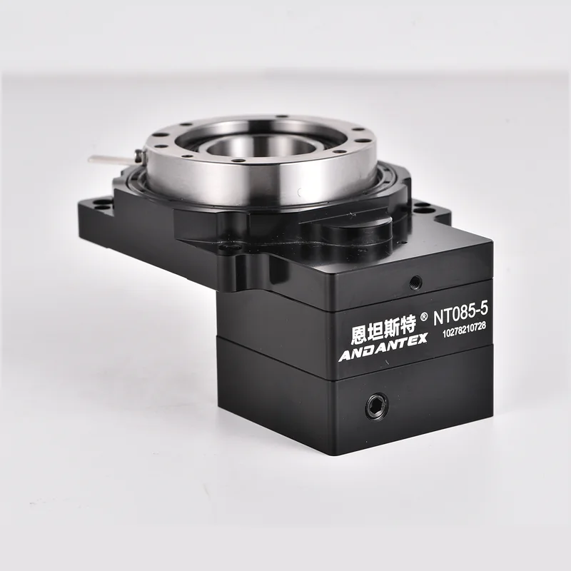
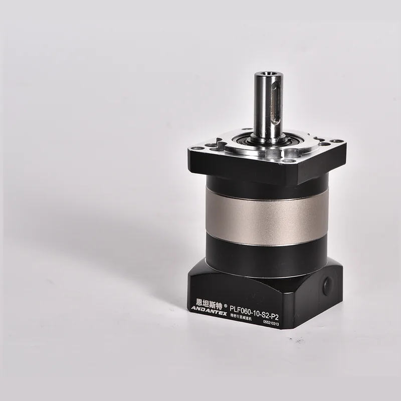
60 Square-Flange Spur Planetary Gearbox, Suitable for compact automation axes, Compatible with 200W–400W Servo and 57 Stepper Motors and Other Motors.

60 Square-Flange Spur Planetary Gearbox, Suitable for compact automation axes, Compatible with 200W–400W Servo and 57 Stepper Motors and Other Motors.
The following specifications are compiled from published website data, Final model-by-model verification by an engineer is recommended.
| Item | Parameters | Description |
|---|---|---|
| Example Model | PLF060-5-S2-P2 | 60 Frame Size / 5:1 / P2 |
| Gear Ratio | 3,4,5,7,10 / 12–100 | L1 / L2 |
| Rated Output Torque | 40 Nm | Example Value |
| Backlash | ≤8 arcmin | Example P2 Stage |
| Maximum Input Speed | 3000 rpm | Monitor Temperature Rise during Continuous Operation |
| Efficiency | 0.95 | Planetary Transmission |
| Operating Temperature | -20℃ ~ +90℃ | Confirm Special Environments Separately |
Calculate the gear ratio from the output speed first, Then check rated torque, Peak Torque, Inertia & Cycle Time.
From Existing 35 Search Engineering Files. Select Motor Type & Stage Count First, Then Use Shaft Diameter, Pilot Diameter, Narrow the Results by Hole Spacing.
Unsure of the Motor Category, Search Directly by Dimensions. If There Is No Exact Match, Submit the motor drawing to confirm a custom interface.
Each card represents one specific configuration“Motor Interface × Number of Stages”. 2D Mounting Drawings & 3D STEP Download Separately, Missing Files Are Clearly Marked.
Confirm L1 / L2, Shaft Diameter & Length, Locating Pilot, Mounting Hole Spacing & Threads. Similar filenames do not mean configurations are interchangeable, Custom output shafts and input flanges require their own resource packages.
Input interfaces and dynamic operating conditions are easily overlooked. In addition to gear ratio and rated torque, Check motor shaft dimensions as well, Pilot Diameter, Hole Spacing, Acceleration & Deceleration Time, Inertia & Offset Loads.
Confirm the shaft diameter against the motor drawing, Shaft Length, Pilot Diameter, Key dimensions including mounting hole spacing, Then determine the input flange and bushing configuration.
Do Not Share Directly. L1 and L2 Stage count and overall length differ, Even When Connected to the Same Motor, Create separate mounting drawings and 3D models.
2D For Dimension Checks, Hole Locations & Tolerances, 3D For Machine Assembly, Interference Checks & Design Reuse; Both files belong to the same configuration package.
Combine the motor interface, Gear Ratio, Output torque and operating conditions in one specification sheet, Reduce repeated clarification.