Skip to content
ANDANTEX / PRECISION TRANSMISSIONSelection Support / 3D Resources / Custom Engineering
Home / Products / Precision Planetary Gearbox / PAG Square-Flange Helical Gearbox / PAG040

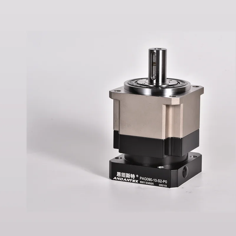
PAG040 Precision Planetary Gearbox

Square-Flange Helical Precision Planetary Gearbox · Low Backlash, High Rigidity, High Repeatability

PAG040PAG Square-Flange Helical Gearbox
PAG SERIES

PAG040

Low Backlash, High Rigidity, High Repeatability. This page provides product configuration information, Engineering Resource Links, Motor Interface Checks, Application & Selection Support.

PAG040Model
Square-Flange Helical Precision Planetary GearboxSeries Structure
TECHNICAL DATA

Models & Technical Resources

Available specifications are shown directly; Other torque specifications, Speed, Refer to official technical documents for load capacity and service life.

AND-PD-PAG040-001 Technical Data SheetSquare-Flange Helical Precision Planetary GearboxPrecision Planetary Gearbox
ItemCurrent DataDescription
Specifications / Frame Size040Model Suffix Size
SeriesPAGANDANTEX Product Series
RATIO OPTIONS

Common Single-Stage Ratios / Two-Stage Ratios

Determine the gear ratio from the required output speed first, Then verify torque, Inertia & Dynamic Operating Conditions.

L1 Single Stage
345710
L2 Two Stage
1215202530354050708090100
INTERFACE

Motor Interface Verification

Motor Shaft Diameter / Shaft Length / Pilot Diameter / Verify hole spacing against the actual motor drawing

Motors with the same power rating may use different interfaces across brands and series.

Open Interface Library
REAL ENGINEERING FILES

PAG040 Engineering Drawing Library

Each interface configuration has one 2D Drawing and one 3D STEP; L1, L2 Managed Separately, Files Are Not Shared.

12Engineering Files
6Interface Resource Package
62D + 3D Complete
0Pending Addition or Confirmation
Loading Resources…Complete resource packages are listed first
No Match Found?Submit Motor Drawing →
DOWNLOAD CHECK

Check stage count and all three interface dimensions before downloading

Must Be Confirmed Together L1 / L2, Shaft Diameter, Pilot Diameter & Mounting Hole Spacing. 8-30-45 and 8-30-46 Only Hole Spacing Differs, Do Not Mix Configurations.

Request Engineering Review
Engineering Resources: 6 Full-Dimension Compressed Images 2D + 6 Files STEPPairing Rules: Interface Dimensions × L1/L2 Managed IndependentlyDashboard Maintenance: Engineering Resources → Replace Individually 2D or 3D
2D DRAWING PREVIEW

PAG040 Mounting Dimensions

PAG040 2D Mounting Drawing Preview

Download Original JPG
APPLICATIONS

Suitable Applications

View Applications →
FAQ

Selection FAQ

PAG040 Can I Order by Model Number Alone?

First confirm the gear ratio, Load, Output Speed, Mounting orientation and motor interface. The same frame size may have different interfaces and configurations.

Drawings and 3D How to Confirm Models?

Find resources on this page or in the Download Center, Confirm the final version against the motor interface and machine mounting dimensions.

What If My Specifications Are Incomplete?

Provide the Motor Model, Load, Target Speed, Required Torque, Cycle Time & Installation Space, Our engineers can help confirm the requirements.

ENGINEERING RFQ

Need a Quote or Engineering Review?

Submit PAG040 Motor Model for, Gear Ratio, Load & Mounting Conditions, Our engineers will review a single consolidated specification sheet.

Generate PAG040 RFQ