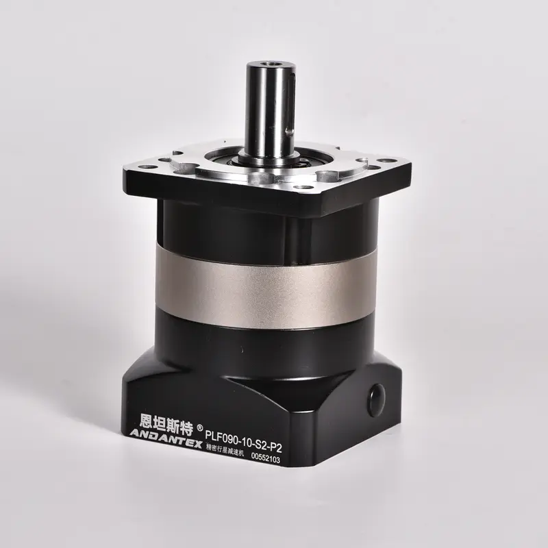
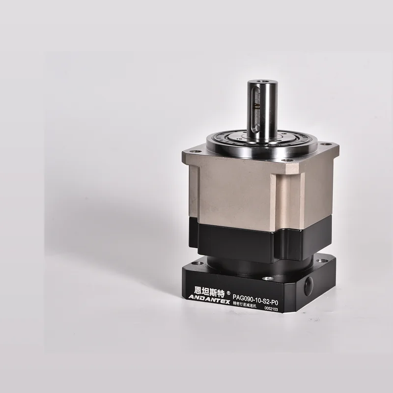
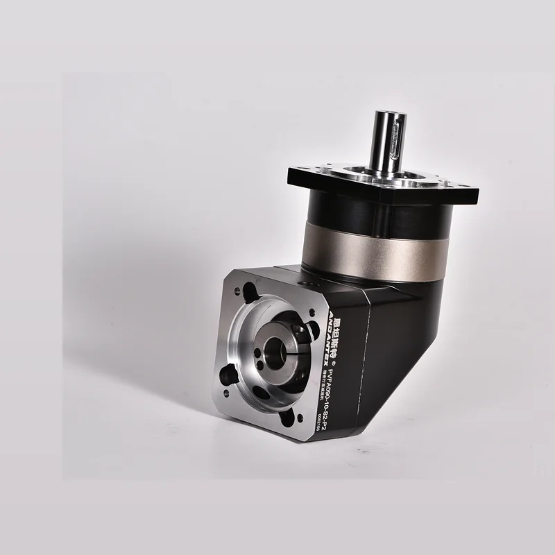
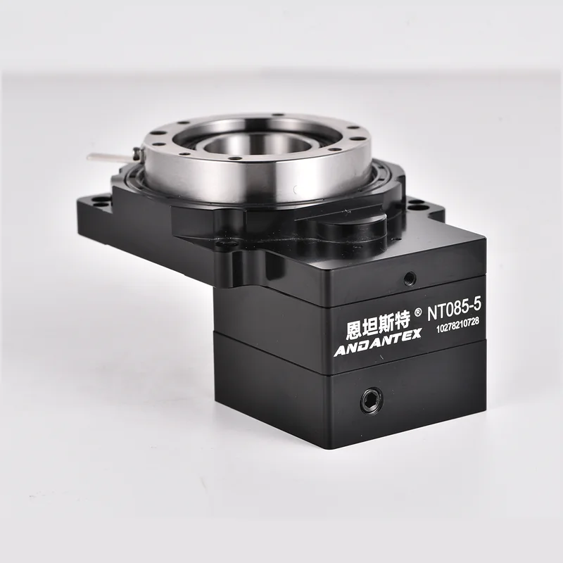
Round-Flange Spur Planetary Gearbox · General Automation, Packaging, Conveying, Dispensing, Screwdriving Applications
General Automation, Packaging, Conveying, Dispensing, Screwdriving Applications. This page provides interface drawings for the round-flange structure, Technical Specifications & Selection Support.
By PLE040 As Entered on the Original Drawing, 3 Ratio Rated Torque Is Only 5-22-43.8 As Marked on the Drawing; Do Not Extrapolate across Interfaces.
| Item | Parameters | Description |
|---|---|---|
| Example Model | PLE040-5-S2-P2 | Example; Confirm the model against the ratio and motor interface |
| Gear Ratio | L1: 3/4/5/7/10; L2: 12/15/16/20/25/28/30/35/40/50/70/100 | L2 of 12, 15 As an Alternative; Rated torque is not specified for some ratios |
| Rated Output Torque | 10–16 Nm(Ratios Specified on the Drawing) | L1 4=16, 5=15, 7=12, 10=10; Only 5-22-43.8 Drawing 3=16, Other L1 Drawing 3 Not Specified. L2 16/25/28/40=16, 20/50=15, 35/70=12, 100=10 Nm |
| Backlash | L1 ≤8 arcmin; L2 ≤12 arcmin | Grouped by Stage Count |
| Rated Speed | 4500 rpm | Annotations on Six 2D Drawings |
| Maximum Input Speed | 8000 rpm | Original 2D Drawing Annotations |
| Efficiency | L1 96%; L2 94% | Grouped by Stage Count |
| Maximum Axial Force | 150 N | 2D Drawing Annotation |
| Maximum Radial Force | 185 N | 2D Drawing Annotation |
| Operating Temperature | -10℃~+90℃ | The Six Verified 2D Drawings |
| IP Rating | IP65 | The Six Verified PLE040 2D Drawings |
| Service Life | 20000 h | Original 2D Drawing Annotations |
| Weight | L1 0.43 kg; L2 0.65 kg | Weight Shown on the Drawing, ±3%; Check against the Corresponding Drawing |
L1: 3/4/5/7/10; L2: 12/15/16/20/25/28/30/35/40/50/70/100. Ratios without rated torque values require separate confirmation; L1 of 3 Ratio Only 5-22-43.8 As Marked on the Drawing 16 Nm.
By Motor Input Shaft Diameter, Find matching files using pilot diameter and mounting hole spacing L1 / L2 Engineering Resources.
Six 2D Mounting Drawings and Six PLE040 STEP Matched by Stage Count & Interface; Including 5-22-43.8 Two original filenames have been corrected after confirmation to PLE040.
6 Original 2D Mounting Drawings and 6 Files PLE040 STEP Paired by Stage Count & Interface; Two Incorrect Original Filenames Corrected.
5-22-43.8 Two Original Files for JPG Filenames Were Previously Incorrect PLF040, Now Confirmed and Corrected to PLE040; Verify the motor interface and final order drawing before use.
First confirm the gear ratio, Load, Output Speed, Mounting orientation and motor interface. The same frame size may have different interfaces and configurations.
Find resources on this page or in the Download Center, Confirm the final version against the motor interface and machine mounting dimensions.
Provide the Motor Model, Load, Target Speed, Required Torque, Cycle Time & Installation Space, Our engineers can help confirm the requirements.
Submit PLE040 Motor Model for, Gear Ratio, Load & Mounting Conditions, Our engineers will review a single consolidated specification sheet.