 PRECISION DRIVE
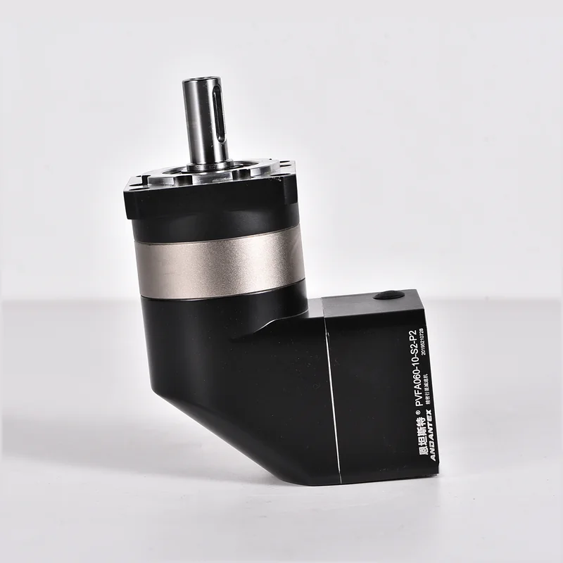
PLF060 Standard Planetary Gearbox
Review the ANDANTEX PLF060 Standard Planetary Gearbox: product specifications, available engineering resources and selection information for your application.
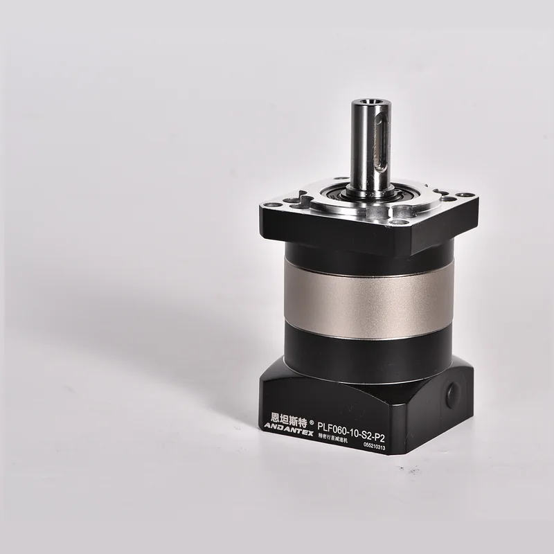
PLF060 Standard Planetary Gearbox
Review the ANDANTEX PLF060 Standard Planetary Gearbox: product specifications, available engineering resources and selection information for your application.
Key Technical Specifications
| Item | Parameters | Description |
|---|---|---|
| Product Series | PLF Square-Flange Spur Gearbox | Standard Planetary Gearbox |
| Specifications / Frame Size | 60 | Model Specifications |
| Example Model | PLF060-5-S2-P2 | 60 Frame Size / 5:1 / P2 |
| Gear Ratio | L1:3/4/5/7/10;L2:12/15/16/20/25/28/30/35/40/50/70/100 | L2 of 12, 15 Marked as an Alternative in the Drawing; See the Next Row for Torque by Ratio |
| Rated Output Torque | 16–40 Nm( By Ratio) | L1:3=27、4/5=40、7=34、10=16;L2:12/15/30=27、16/20/25/28/35/40/50=40、70=34、100=16 Nm |
| Maximum Torque | Of the Rated Output Torque 1.5 Times | Maximum Output Torque Specified in the Drawing, Varies with the Rated Value for Each Ratio |
| Backlash | L1 ≤8 arcmin;L2 ≤12 arcmin | Standard Backlash; Select Drawing by Stage Count |
| Maximum Input Speed | 8000 rpm | Maximum Input Speed Specified in the Drawing |
| Rated Input Speed | 4000 rpm | Rated Input Speed Specified in the Drawing |
| Efficiency | L1 96%;L2 94% | Two-Stage Efficiency Differs |
| Operating Temperature | Standard Interface -10℃~+90℃ | Some Custom Interface Drawings Specify -20℃~+80℃; Use the Specific Interface Drawing |
| Maximum Axial Force | 220 N | 2D Maximum Axial Force Specified in the Drawing |
| Maximum Radial Force | 240 N | 2D Maximum Radial Force Specified in the Drawing |
| Weight | L1 0.98 kg;L2 1.26 kg | As Shown 14-50-70 Motor Interface, ±3%; Confirm Other Interfaces against Their Engineering Drawings |
| IP Rating | IP65 | Verified L1/L2 Standard Interface Drawing |
| Service Life | 20000 h | Service Life Specified in the Drawing |
Unlisted Specifications Are Pending, Confirm for the Specific Configuration.
Specifications / Gear Ratio
L1:3/4/5/7/10;L2:12/15/16/20/25/28/30/35/40/50/70/100
L2 of 12, 15 Marked as an Alternative in the Drawing; See the Next Row for Torque by Ratio
Gear Ratio, Confirm Stages & Interface Using the Required Configuration and Official Drawing.
Find by Interface Dimensions PLF060 Drawings
The Same Model Can Store Separate Servo, Stepper, Custom and Different L1/L2 Configurations; Options Expand Automatically as Engineering Resources Are Published.
Enter Motor Shaft Diameter, Pilot Diameter & Mounting Hole Spacing, Find identical or similar input interfaces across recorded models; Resources Requiring Review Are Clearly Marked.
Match Using Dimensions on the Motor Drawing
Select the Motor Type in Order, Stages, Shaft Diameter, Pilot Diameter & Hole Spacing; Results Are Listed by Interface 2D Drawings and 3D STEP, Missing Files Are Marked as Pending.
PLF060 2D / 3D Engineering Resources
Each Standard Size, Motor Interface & Custom Combination Is Managed Separately 2D Drawing and 3D STEP; 2D Supports Images and PDF.
Check the Model before Downloading, Size & Interface
Use the Current Order Model & Official Engineering Drawing; Custom Input, Outputs & Flanges Require Their Own Resources.
Selection FAQ
Select PLF060 What Is Commonly Overlooked When Selecting a Planetary Gearbox?
Input interfaces and dynamic operating conditions are easily overlooked. In addition to gear ratio and rated torque, Check motor shaft dimensions as well, Pilot Diameter, Hole Spacing, Acceleration & Deceleration Time, Inertia & Offset Loads.
Can the Interface Be Customized for Other Motor Brands?
Confirm the shaft diameter against the motor drawing, Shaft Length, Pilot Diameter, Key dimensions including mounting hole spacing, Then determine the input flange and bushing configuration.
L1 and L2 Can They Share the Same 2D or 3D Drawing?
Do Not Share Directly. L1 and L2 Stage count and overall length differ, Even When Connected to the Same Motor, Create separate mounting drawings and 3D models.
Why Store Both Files for a Stepper Interface 2D and 3D?
2D For Dimension Checks, Hole Locations & Tolerances, 3D For Machine Assembly, Interference Checks & Design Reuse; Both files belong to the same configuration package.
Need a Quote or Engineering Review?
Submit PLF060 Gear Ratio for, Load & Installation Requirements.