 PRECISION DRIVE
PAMG060 Right-Angle Helical Planetary Gearbox | for Automation Drives
The ANDANTEX PAMG060 right-angle helical planetary gearbox combines a square output flange with a 16 mm shaft output. Supplied L1 and L2 drawings cover rated output torques from 30 to 45 Nm, depending on ratio. Motor interfaces include 11-50-70, 14-50-70 and 8-38.1-66.7 mm. Backlash varies by interface and stage; use the exact drawing when matching a motor and checking installation dimensions.
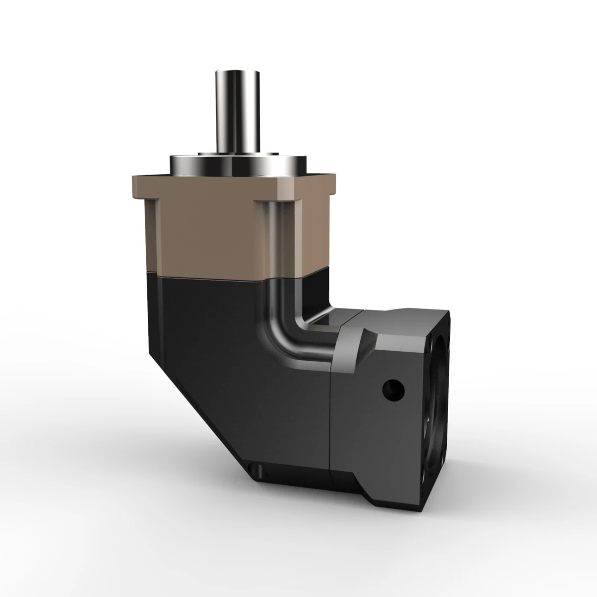
PAMG060 Right-Angle Helical Planetary Gearbox | for Automation Drives
The ANDANTEX PAMG060 right-angle helical planetary gearbox combines a square output flange with a 16 mm shaft output. Supplied L1 and L2 drawings cover rated output torques from 30 to 45 Nm, depending on ratio. Motor interfaces include 11-50-70, 14-50-70 and 8-38.1-66.7 mm. Backlash varies by interface and stage; use the exact drawing when matching a motor and checking installation dimensions.
Key Technical Specifications
| Item | Parameters | Description |
|---|---|---|
| Product Series | PAMG Right-Angle Helical Gearbox | Precision Planetary Gearbox |
| Specifications / Frame Size | 060 | Model Specifications |
| Output Structure / Flange Type | Right-angle input; square flange; 16 mm shaft output | Dimensions depend on the selected motor adapter. |
| Gear Ratio | L1: 3, 4, 5, 7, 8, 10, 14, 20; L2: 25, 30, 35, 40, 50, 70, 100 | Ratios listed with torque values in the supplied drawings. |
| Rated Output Torque | 30-45 Nm | L1: 3=40 Nm; 4/5/7/8/10/14=45 Nm; 20=30 Nm. L2: 30=40 Nm; 25/35/40/50/70/100=45 Nm. |
| Maximum Torque | 1.5 x rated output torque | Use the rated torque for the selected ratio. |
| Backlash | L1: <=5 or <=8 arcmin; L2: <=7 arcmin | L1 14-50-70: <=5; L1 11-50-70 and 8-38.1-66.7: <=8 arcmin. |
| Maximum Input Speed | 8000 rpm | Maximum input speed from supplied drawings. |
| Rated Speed | 4000 rpm | Rated input speed. |
| Efficiency | L1 95%; L2 92% | Values from the corresponding stage drawings. |
| Operating Temperature | -10 to +90 C | Supplied drawing specification. |
| Maximum Axial Force | 600 N | Confirm load position and duty cycle for the application. |
| Maximum Radial Force | 1530 N | Confirm load position and duty cycle for the application. |
| Weight | L1 2.05 kg; L2 3.15 kg | Drawing tolerance +/-3%. |
| Typical Interface | 11-50-70; 14-50-70; 8-38.1-66.7 mm | Shaft-pilot-PCD. The L1 8 mm drawing dimension shows PCD66.7, but its footer says66.4; confirm this interface before ordering. |
| IP Rating | IP65 | Supplied drawing specification. |
| Service Life | 20000 h | Drawing specification; actual life depends on operating conditions. |
Unlisted Specifications Are Pending, Confirm for the Specific Configuration.
Specifications / Gear Ratio
L1: 3, 4, 5, 7, 8, 10, 14, 20; L2: 25, 30, 35, 40, 50, 70, 100
Ratios listed with torque values in the supplied drawings.
Gear Ratio, Confirm Stages & Interface Using the Required Configuration and Official Drawing.
Find by Interface Dimensions PAMG060 Drawings
The Same Model Can Store Separate Servo, Stepper, Custom and Different L1/L2 Configurations; Options Expand Automatically as Engineering Resources Are Published.
Enter Motor Shaft Diameter, Pilot Diameter & Mounting Hole Spacing, Find identical or similar input interfaces across recorded models; Resources Requiring Review Are Clearly Marked.
Match Using Dimensions on the Motor Drawing
Select the Motor Type in Order, Stages, Shaft Diameter, Pilot Diameter & Hole Spacing; Results Are Listed by Interface 2D Drawings and 3D STEP, Missing Files Are Marked as Pending.
PAMG060 2D / 3D Engineering Resources
Each Standard Size, Motor Interface & Custom Combination Is Managed Separately 2D Drawing and 3D STEP; 2D Supports Images and PDF.
Check the Model before Downloading, Size & Interface
Use the Current Order Model & Official Engineering Drawing; Custom Input, Outputs & Flanges Require Their Own Resources.
Selection FAQ
PAMG060 Can I Order by Model Number Alone?
First confirm the gear ratio, Load, Output Speed, Mounting orientation and motor interface. The same frame size may have different interfaces and configurations.
Drawings and 3D How to Confirm Models?
Find resources on this page or in the Download Center, Confirm the final version against the motor interface and machine mounting dimensions.
What If My Specifications Are Incomplete?
Provide the Motor Model, Load, Target Speed, Required Torque, Cycle Time & Installation Space, Our engineers can help confirm the requirements.
Need a Quote or Engineering Review?
Submit PAMG060 Gear Ratio for, Load & Installation Requirements.