Skip to content
ANDANTEX / PRECISION TRANSMISSIONSelection Support / 3D Resources / Custom Engineering
Home / Products / PAG Precision Planetary / PAG120

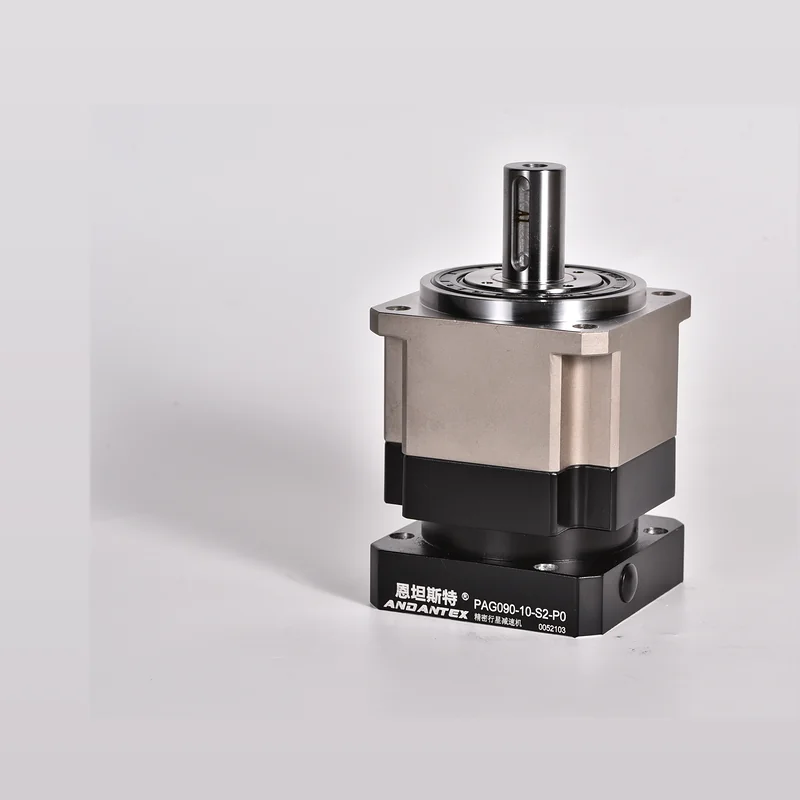
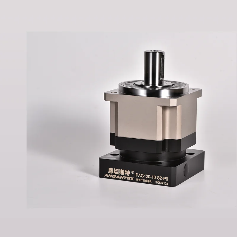
PAG120 Precision Planetary Gearbox

120 Frame Size · Square-Flange Helical · Low-Backlash Precision Type

Product PhotoPAG120 Planetary Gearbox
PAG PRECISION SERIES

PAG120

✓ Current website specifications have been reviewed

Square-Flange Helical Planetary, Rated Output Torque 230 Nm, Backlash 3 arcmin, Suitable for Rigidity Requirements, Automation axes requiring low backlash and stable positioning.

Legacy Data Review: Current Legacy Website PAG120 Page Title, Specifications and 3D All Files Refer to PAG120, But“Model”The Field Was Incorrectly Entered as PAG090. The Updated Version Uses PAG120 Archive.
230 NmRated Output Torque
3 arcminBacklash
6700 NMaximum Radial Force
3000 NMaximum Axial Force
8000 rpmMaximum Input Speed
0.95Efficiency
TECHNICAL DATA

Key Technical Specifications

Data from the current ANDANTEX Compiled from published official website pages, Managed using the updated field structure during migration.

AND-PD-PAG120-001 Technical Data Sheet Square-Flange Helical Planetary Torque: 230 Nm Accuracy: 3 arcmin
ItemParametersDescription
Series / Frame SizePAG / 120Square-Flange Helical
Example Gear Ratio5The series also offers 3/4/7/10 And two-stage ratios
Backlash3 arcminLow-Backlash Precision Applications
Rated Output Torque230 NmVerify continuous operation for the chosen ratio
Maximum Radial Force6700 NCalculate using the load application point
Maximum Axial Force3000 NCheck carefully when thrust loads are present
Torsional Rigidity23 Nm/arcminAffects dynamic positioning and resistance to torsional deformation
Maximum Input Speed8000 rpmMonitor temperature rise during continuous high-speed operation
Typical InterfaceExample Shaft Diameter 22 / Pilot Diameter 110 / Hole Spacing 145Confirm against the actual motor drawing
RATIO OPTIONS

Single Stage / Two-Stage Ratios

Calculate the gear ratio from the output speed first, Then check rated torque, Peak Torque, Inertia & Cycle Time.

L1 Single StageCommon Gear Ratios
345710
L2 Two StageCommon Gear Ratios
1215202530354050708090100
MOTOR INTERFACE DATABASE

PAG120 Common Motor Interface Combinations

Currently Listed 3 Interface Groups, Including 1 Groups with Verified Examples. Final orders must be verified against the motor drawing.

Search Interfaces across Models
Interface CodeShaft DiameterLocating PilotMounting Hole SpacingTypical MotorDescriptionStatus
22-110-145
L1
22 mm 110 mm 145 mm Medium- & High-Power Servo PAG120 Common Interface Example Verified Example
24-95-115
L1
24 mm 95 mm 115 mm Large-Shaft Servo Large-Shaft Interface Candidate Additional Candidates
19-95-130
L1
19 mm 95 mm 130 mm Medium-Power Servo Medium-Power Interface Candidate Additional Candidates
Interface codes use“Shaft Diameter-Pilot Diameter-Hole Spacing”A simplified format; Also check shaft length for each motor, Keyway, Mounting Threads & Flange Thickness.
ENGINEERING FILES

Engineering Drawings & Selection Resources

2D, 3D Motor interfaces are managed under the same product model, Different motor interfaces do not require duplicate product pages.

Data Document: AND-PD-PAG120-001 Version: V1.0 Update: 2026-09 Suitable for: PAG120 Published Series Specifications & Interface Examples
APPLICATIONS

PAG120 Typical Applications

View All Applications →
SELECTION

Why Choose PAG, Instead of a Conventional Spur Gearbox PLF?

Lower Backlash

PAG The current published example is 3 arcmin, Suitable for Indexing, Inspection, Assembly & High-Repeatability Applications.

Higher Load Capacity & Rigidity

Radial/Higher axial load capacity and torsional rigidity, Suitable for axes requiring higher structural rigidity.

Only Have a Motor Drawing?Select a Gearbox from Motor Requirements

Input Power, Shaft Diameter, Pilot Diameter, Hole Spacing, Structure & Torque Requirements, The system provides candidate models first, An engineer then reviews the selection.

Open Motor-Based Selection
FAQ

Selection FAQ

PAG120 Can I Select by Motor Power Alone?

No. Also consider the output speed, Load Torque, Peak Torque, Inertia, Confirm acceleration/deceleration time and motor interface together.

How to Verify the Motor Interface?

At minimum, check shaft diameter, Shaft Length/Keyway, Pilot Diameter & Mounting Hole Spacing, Confirm threads and flange thickness when necessary.

2D / 3D How to Obtain Resources?

Open the current resource page from the engineering resources section; For actual projects, confirm the final drawing version for the specific motor interface.

Need a Quote or Engineering Review?Generate PAG120 RFQ

Combine the motor interface, Gear Ratio, Output torque and operating conditions in one specification sheet, Reduce repeated clarification.

Generate PAG120 RFQ