PDFMANUAL
BLD Series Brushless DC Motor Driver Manual
BLD series brushless DC motor driver functions, wiring and operating settings. Chinese edition A00.
View / Download PDF PRECISION DRIVE
1500 W · 48 V DC · 39 A · 3000 rpm · 4.8 N·m. Ø19×40 mm output shaft, Ø95 mm pilot and PCD125 mm mounting pattern. PDF drawing, STEP model and BLD driver manual available.
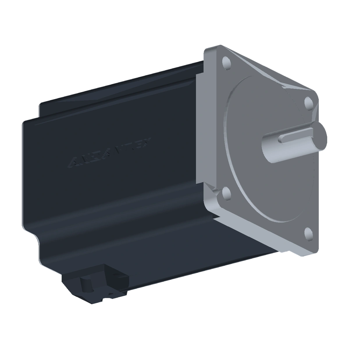
D110BLD1500-48A-30S Mounting dimensions: 110×110 mm square flange; Ø19 mm output shaft with 40 mm extension; Ø95 mm pilot, 2 mm high; four Ø9.5 mm through holes on PCD125 mm. Motor body length 153 mm; keyway 6 mm wide and 25 mm long. Wiring: power leads — thick red U, thick yellow V, thick black W. Hall leads — thin red 5V, thin black GND, thin blue Hu, thin green Hv, thin white HW. Operating environment: IP54; ambient temperature 0–50°C; ambient humidity below 90%.
| Item | Parameters | Description |
|---|---|---|
| Product Series | BLD Brushless DC Motors | Brushless DC Motor |
| Specifications / Frame Size | 110 | Model Specifications |
| Output Structure / Flange Type | 110×110 mm square flange; Ø19×40 mm keyed output shaft | — |
| Rated Output Torque | 4.8 N·m | — |
| Rated Speed | 3000 rpm | — |
| Rated Power | 1500 W | — |
| Motor Flange | 110×110 mm | — |
| Operating Temperature | 0–50°C | — |
| Typical Interface | Ø19 shaft × 40 mm; Ø95 pilot × 2 mm; PCD125, 4-Ø9.5 through holes | — |
| IP Rating | IP54 | — |
Need a specification that is not listed? Contact us with the required configuration.
Select the motor interface and reduction stage to find the matching drawing and STEP model.
Enter the motor shaft diameter, pilot diameter and mounting-hole spacing to compare input interfaces across models.
Filter by motor type, reduction stage and mounting dimensions. Open the available files, or request the format you need.
Download catalogs and manuals applicable to this product. For mounting dimensions and CAD models, see the 2D / 3D section below.
BLD series brushless DC motor driver functions, wiring and operating settings. Chinese edition A00.
View / Download PDFChoose your configuration below. Use the 2D drawing to check dimensions and the STEP model to check fit in your assembly.
Match the model, reduction stage and motor interface to the drawing. Custom input or output dimensions require a separate set of files.
Provide the Load, Target Output Speed, Start/Stop Cycle, Installation Space & Operating Environment, Confirm Whether This Model Is Suitable.
View ApplicationsCheck Motor Shaft Diameter, Shaft Length, Keyway, Pilot Diameter & Mounting Hole Locations, Use the Official Drawing for the Matching Configuration.
Submit the Model & Required Configuration for Engineering Review, Unpublished resources do not mean the configuration has been verified.
Send the required ratio, motor drawing, load and installation details for D110BLD1500-48A-30S.
Get a Quote
Share your email and requirements for pricing or selection support.