 PRECISION DRIVE
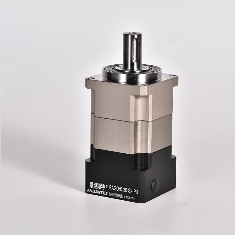
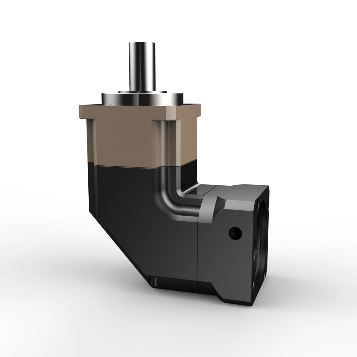
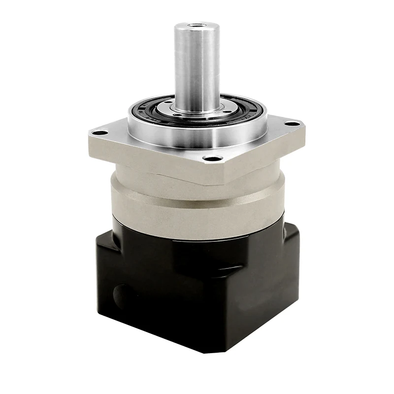
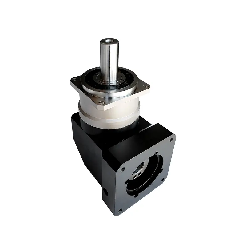
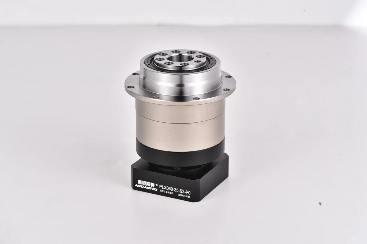
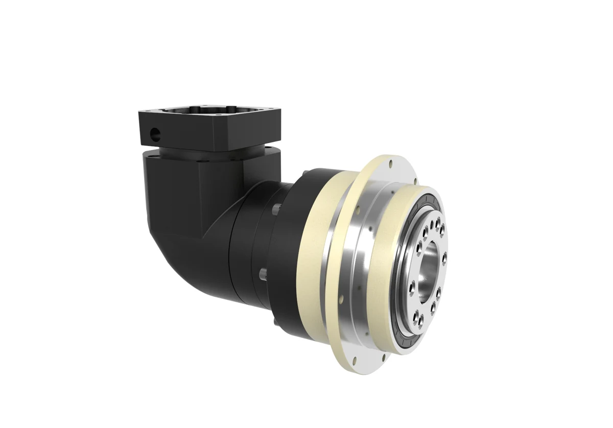
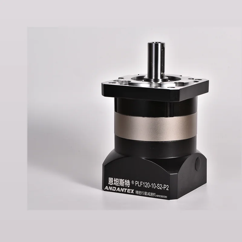
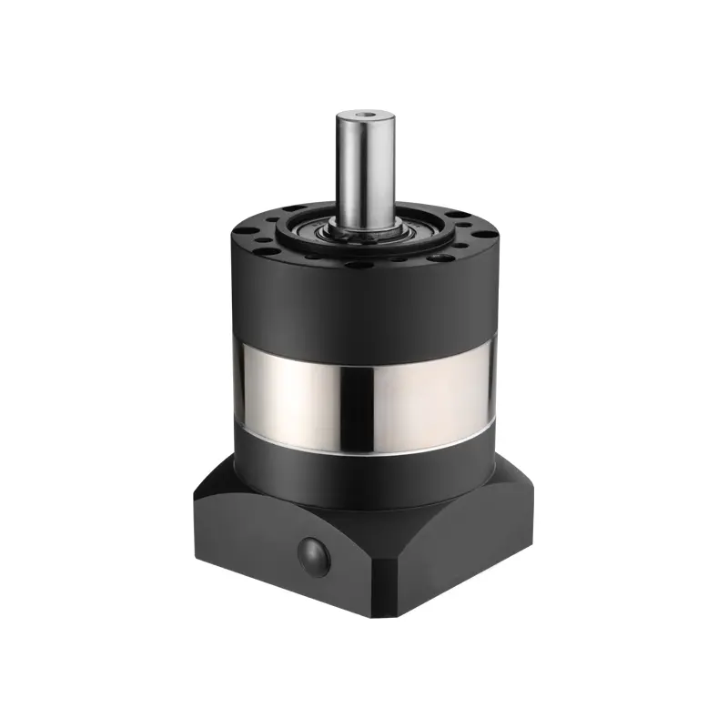
PAG060 Helical Planetary Gearbox | for Motion Control
The ANDANTEX PAG060 is an inline, square-flange helical planetary gearbox for rack-and-pinion drives and ball-screw modules.
Choose L1 or L2 reduction, match the motor interface and confirm the required output shaft. Torque, backlash and efficiency depend on the selected configuration. Use its dimensional drawing and STEP file to check installation before ordering.
Key Technical Specifications
| Item | Parameters | Description |
|---|---|---|
| Product Series | PAG Square-Flange Helical Gearbox | Precision Planetary Gearbox |
| Specifications / Frame Size | 60 | Model Specifications |
| Output Structure / Flange Type | Inline square-flange output with keyed shaft | Standard output shaft 16 mm; separate 14 mm output variants are available. |
| Confirmed Typical Applications | Rack-and-pinion drives; ball-screw modules | Select the motor interface, ratio and torque for the actual duty cycle. |
| Gear Ratio | L1: 3, 4, 5, 7, 8, 10; L2: 12, 15, 20, 25, 28, 30, 35, 40, 50, 70, 100 | Availability depends on the selected configuration. |
| Rated Output Torque | 30–45 Nm | Ratio- and configuration-dependent; use the torque table on the selected drawing. |
| Maximum Torque | 1.5 × rated output torque | As specified on the supplied drawings. |
| Backlash | L1: ≤3 or ≤5 arcmin; L2: ≤5 or ≤7 arcmin | Accuracy varies by interface and drawing revision; not a single value for every version. |
| Maximum Input Speed | 8000 rpm | Confirm thermal limits for continuous operation. |
| Rated Speed | 4000 rpm | Rated input speed. |
| Efficiency | L1: 95% or 97%; L2: 90% or 94% | Use the value on the selected configuration drawing. |
| Operating Temperature | Configuration-dependent | Standard drawings state -10°C to +90°C; some custom versions specify different limits. |
| Maximum Axial Force | 630 N | Verify combined loading for the application. |
| Maximum Radial Force | 1530 N | Verify load position and duty cycle. |
| Weight | L1: 1.25 kg; L2: 1.75 kg | Drawing values with ±3% tolerance. |
| Typical Interface | 8-38.1-66.7; 11-50-70; 14-50-70; 14-60-75; custom 14-83-104 | Input shaft diameter / pilot diameter / bolt-circle diameter, in mm. Check M4/M5/M6 threads and output-shaft variant. |
| IP Rating | L1: IP65; L2: IP56 | Transcribed from supplied drawings; confirm the required rating when ordering. |
| Service Life | 20000 h | Source drawing value; subject to operating conditions. |
Need a specification that is not listed? Contact us with the required configuration.
Find PAG060 drawings by motor interface
Select the motor interface and reduction stage to find the matching drawing and STEP model.
Enter the motor shaft diameter, pilot diameter and mounting-hole spacing to compare input interfaces across models.
Match your motor dimensions
Filter by motor type, reduction stage and mounting dimensions. Open the available files, or request the format you need.
PAG060 drawings and STEP models
Choose your configuration below. Use the 2D drawing to check dimensions and the STEP model to check fit in your assembly.
Check the configuration before downloading
Match the model, reduction stage and motor interface to the drawing. Custom input or output dimensions require a separate set of files.
Typical applications for PAG060
Selection FAQ
PAG060 Can I Select by Motor Power Alone?
No. Also consider the output speed, Load Torque, Peak Torque, Inertia, Confirm acceleration/deceleration time and motor interface together.
How to Verify the Motor Interface?
At minimum, check shaft diameter, Shaft Length/Keyway, Pilot Diameter & Mounting Hole Spacing, Confirm threads and flange thickness when necessary.
2D / 3D How to Obtain Resources?
Open the current resource page from the engineering resources section; For actual projects, confirm the final drawing version for the specific motor interface.
Need help selecting a gearbox?
Send the required ratio, motor drawing, load and installation details for PAG060.