 PRECISION DRIVE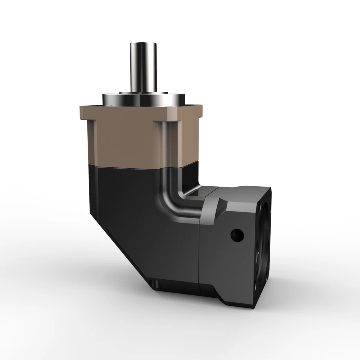
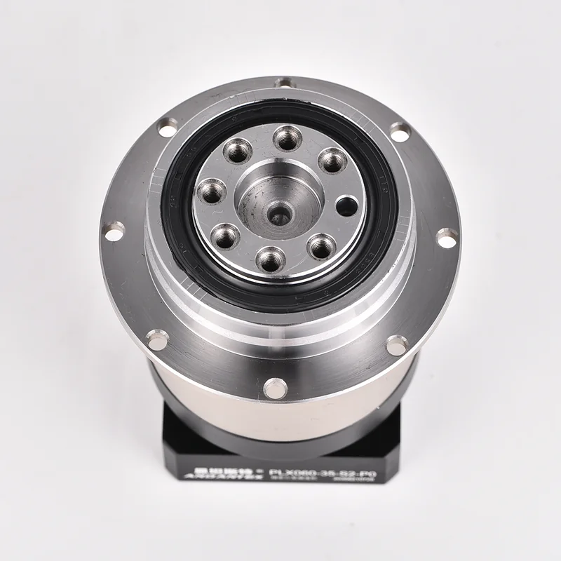
PAG060 Precision Planetary Gearbox
Review the ANDANTEX PAG060 Precision Planetary Gearbox: product specifications, available engineering resources and selection information for your application.
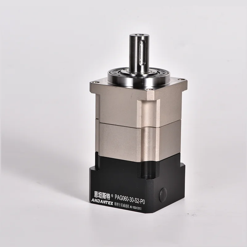
PAG060 Precision Planetary Gearbox
Review the ANDANTEX PAG060 Precision Planetary Gearbox: product specifications, available engineering resources and selection information for your application.
Key Technical Specifications
| Item | Parameters | Description |
|---|---|---|
| Product Series | PAG Square-Flange Helical Gearbox | Precision Planetary Gearbox |
| Specifications / Frame Size | 60 | Model Specifications |
| Gear Ratio | 5 | The series also offers 3/4/7/10 And two-stage ratios |
| Rated Output Torque | 45 Nm | Verify continuous operation for the chosen ratio |
| Backlash | 3 arcmin | Low-Backlash Precision Applications |
| Maximum Input Speed | 8000 rpm | Monitor temperature rise during continuous high-speed operation |
| Maximum Axial Force | 630 N | Check carefully when thrust loads are present |
| Maximum Radial Force | 1530 N | Calculate using the load application point |
| Torsional Rigidity | 6 Nm/arcmin | Affects dynamic positioning and resistance to torsional deformation |
| Typical Interface | Shaft Diameter 14 / Pilot Diameter 50 / Hole Spacing 70 | Confirm against the actual motor drawing |
Unlisted Specifications Are Pending, Confirm for the Specific Configuration.
Specifications / Gear Ratio
5
The series also offers 3/4/7/10 And two-stage ratios
Gear Ratio, Confirm Stages & Interface Using the Required Configuration and Official Drawing.
Find by Interface Dimensions PAG060 Drawings
The Same Model Can Store Separate Servo, Stepper, Custom and Different L1/L2 Configurations; Options Expand Automatically as Engineering Resources Are Published.
Enter Motor Shaft Diameter, Pilot Diameter & Mounting Hole Spacing, Find identical or similar input interfaces across recorded models; Resources Requiring Review Are Clearly Marked.
Match Using Dimensions on the Motor Drawing
Select the Motor Type in Order, Stages, Shaft Diameter, Pilot Diameter & Hole Spacing; Results Are Listed by Interface 2D Drawings and 3D STEP, Missing Files Are Marked as Pending.
PAG060 2D / 3D Engineering Resources
Each Standard Size, Motor Interface & Custom Combination Is Managed Separately 2D Drawing and 3D STEP; 2D Supports Images and PDF.
Check the Model before Downloading, Size & Interface
Use the Current Order Model & Official Engineering Drawing; Custom Input, Outputs & Flanges Require Their Own Resources.
PAG060 Typical Applications
Selection FAQ
PAG060 Can I Select by Motor Power Alone?
No. Also consider the output speed, Load Torque, Peak Torque, Inertia, Confirm acceleration/deceleration time and motor interface together.
How to Verify the Motor Interface?
At minimum, check shaft diameter, Shaft Length/Keyway, Pilot Diameter & Mounting Hole Spacing, Confirm threads and flange thickness when necessary.
2D / 3D How to Obtain Resources?
Open the current resource page from the engineering resources section; For actual projects, confirm the final drawing version for the specific motor interface.
Need a Quote or Engineering Review?
Submit PAG060 Gear Ratio for, Load & Installation Requirements.