 PRECISION DRIVE
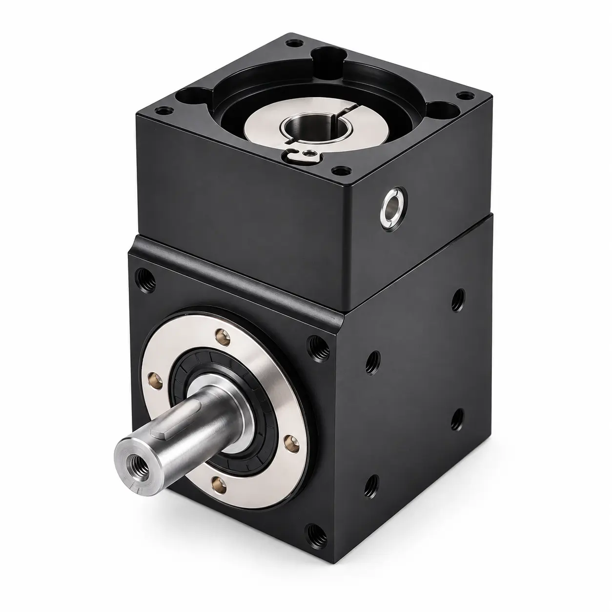
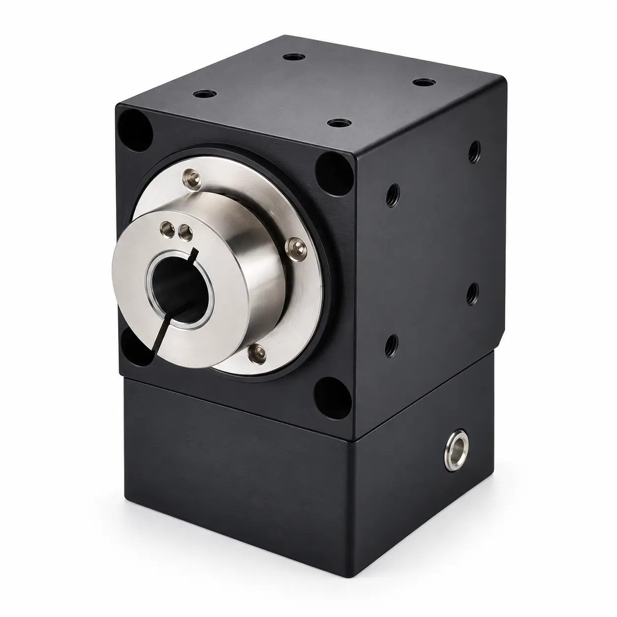
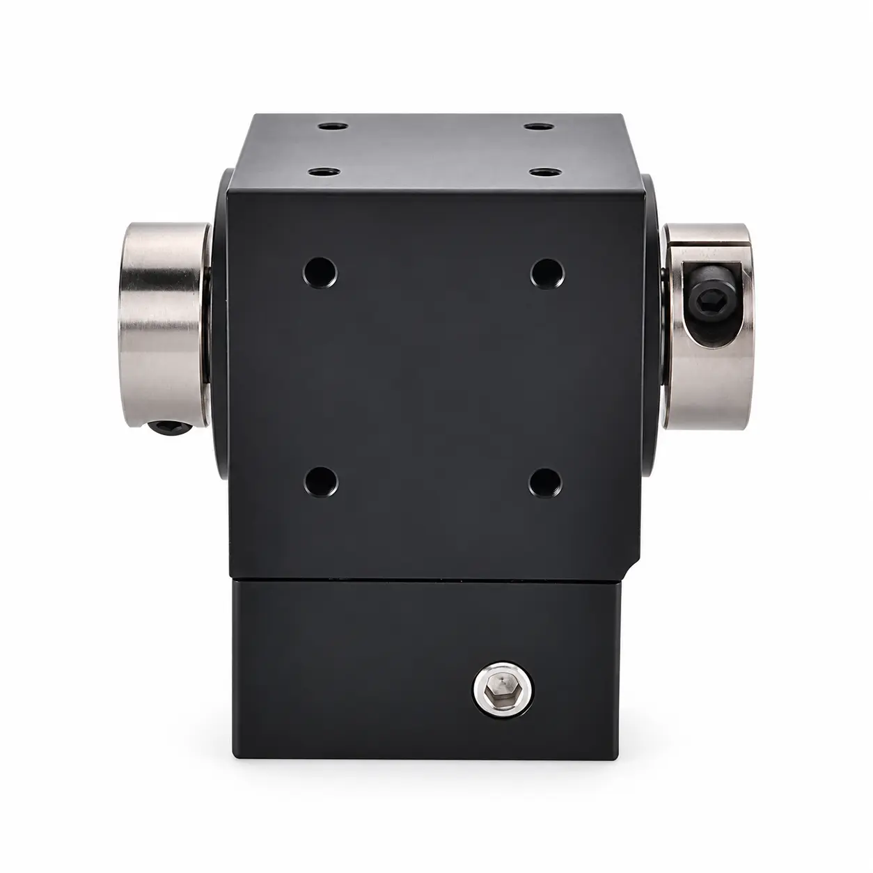
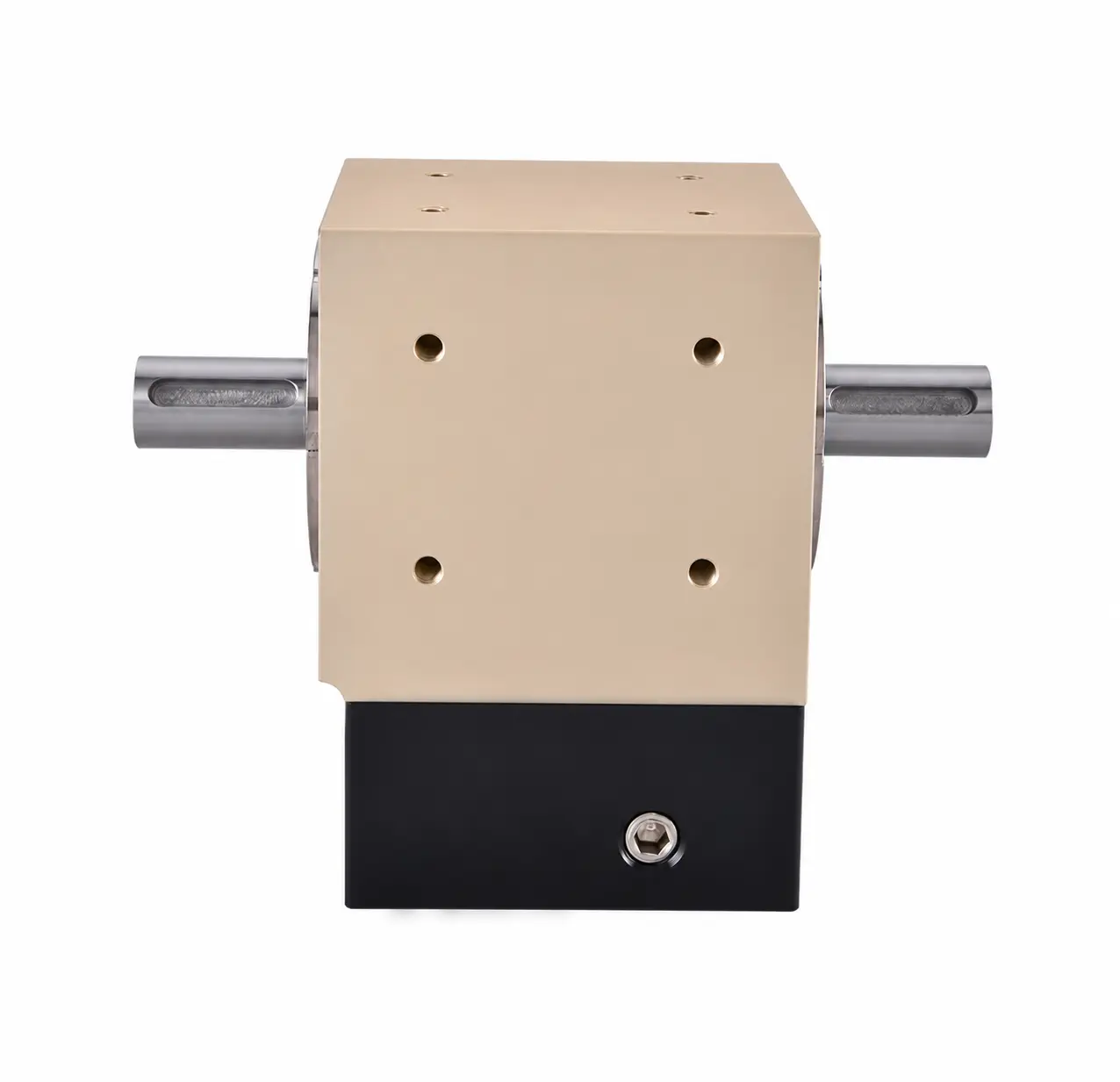
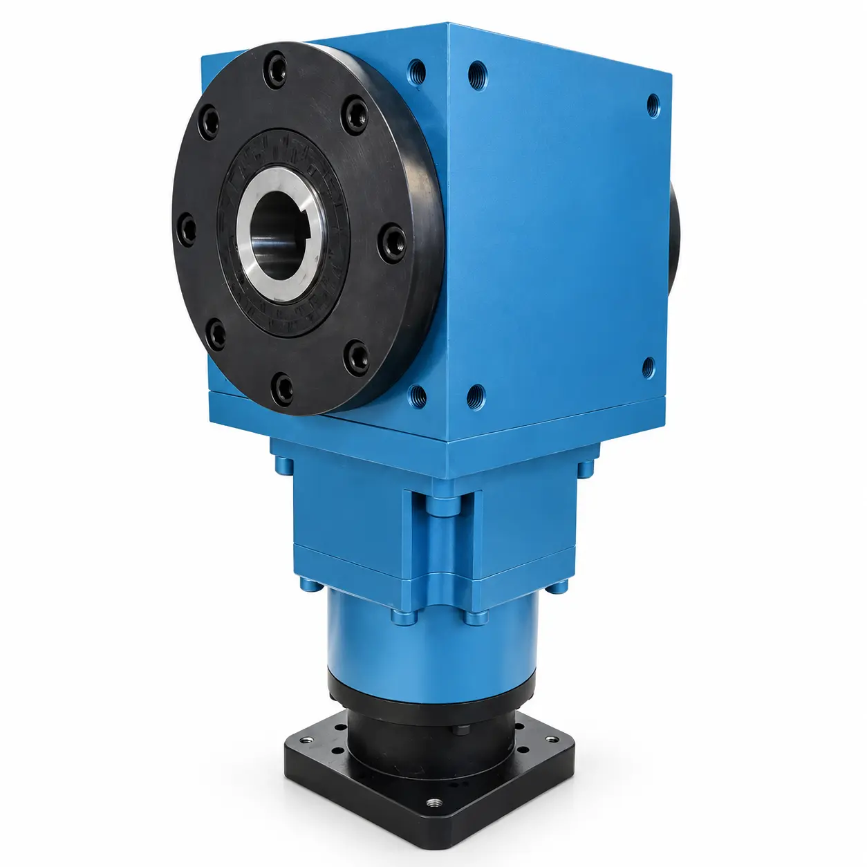
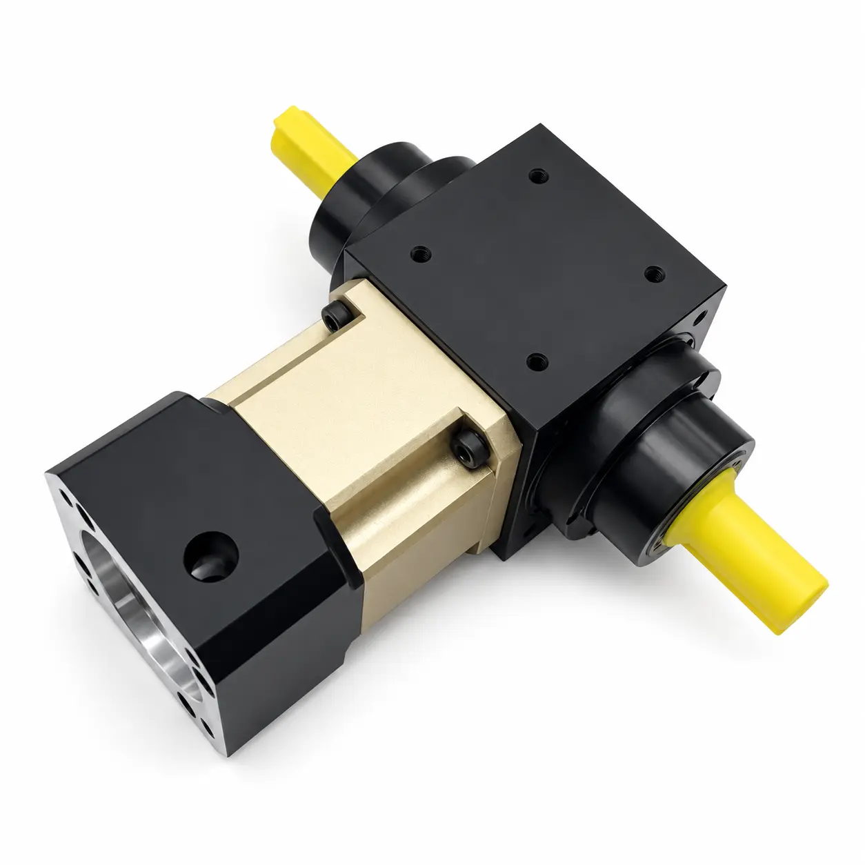
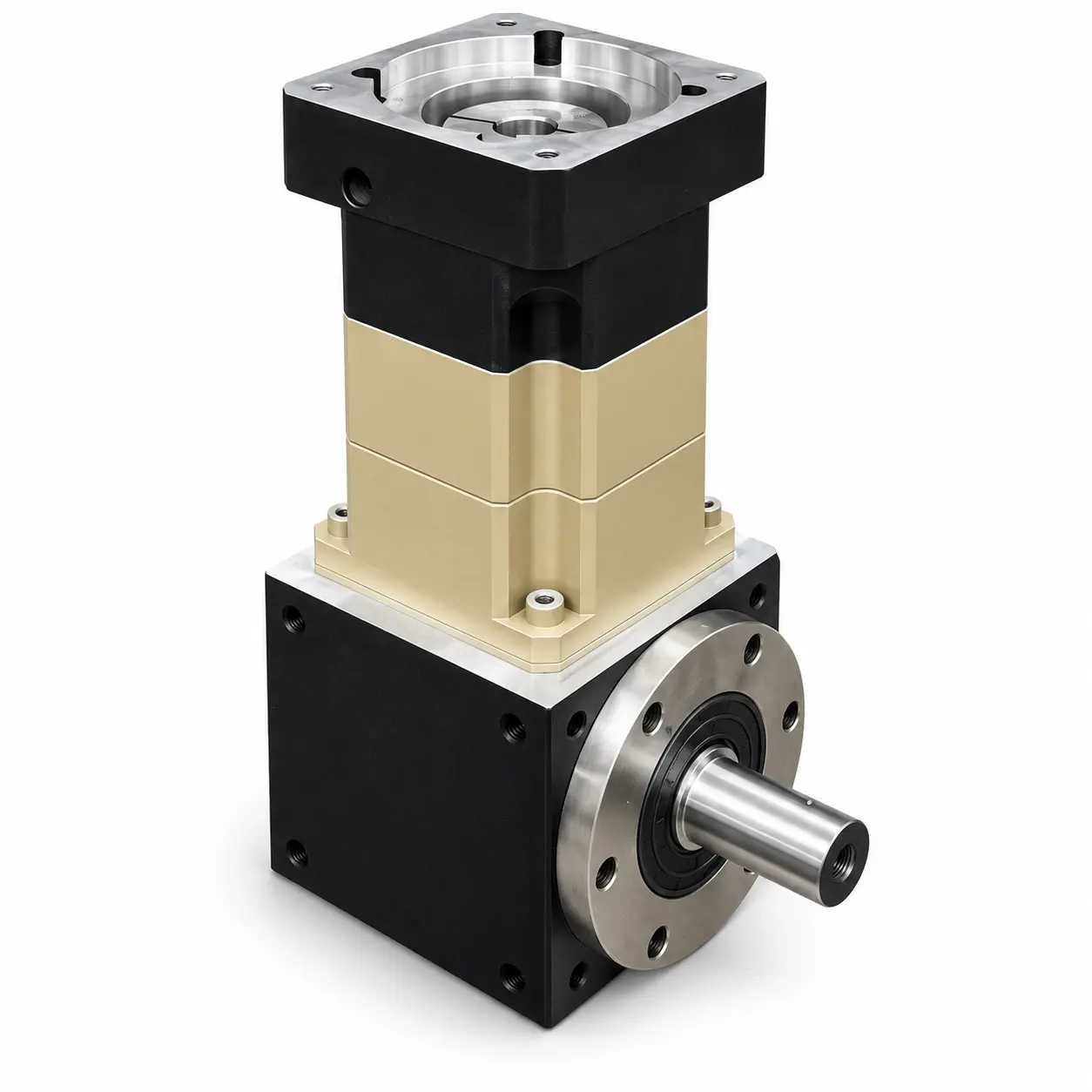
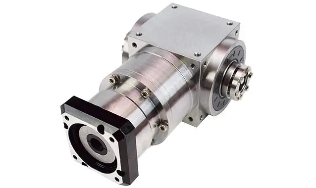
PVFG040 Double-Bore Output Right-Angle Gearbox
The ANDANTEX PVFG040 is a right-angle gearbox with coupling-bore input and double-bore output.
Review L1 and L2 configurations, output torque by ratio and motor interfaces using the available dimensional drawings and STEP models. Confirm the required output arrangement and mounting dimensions before ordering. Both output sides can drive loads simultaneously. The rated output torque is the combined limit for both sides, not a separate full rating for each side. Confirm the load on each side for the selected configuration.
Key Technical Specifications
| Item | Parameters | Description |
|---|---|---|
| Product Series | PVFG Double-Bore Output Right-Angle Gearbox | Right Angle Gearbox |
| Specifications / Frame Size | 040 | Model Specifications |
| Output Structure / Flange Type | Coupling-bore input; double-bore output; right-angle transmission | Both output sides can connect loads simultaneously. Match the mounting and connection dimensions to the selected drawing. |
| Gear Ratio | L1: 2, 3, 5; L2: 10, 12, 15, 20, 25, 30, 35, 50 | Based on supplied L1 and L2 drawings. |
| Rated Output Torque | 18–23 Nm | L1: 2=23, 3=20, 5=18 Nm. L2: 10=23, 12=20, 15=20, 20=23, 25=18, 30=20, 35=20, 50=18 Nm. Both output sides can drive loads simultaneously. The rated output torque is the combined limit for both sides, not a separate full rating for each side. Confirm the load on each side for the selected configuration. |
| Maximum Torque | L1: 2 × rated torque; L2: 1.5 × rated torque | Per supplied drawings; verify the selected ratio and duty cycle. |
| Backlash | L1: ≤5 arcmin; L2: ≤8 arcmin | Per supplied drawings. |
| Maximum Input Speed | 3000 rpm | L1 and L2 drawings. |
| Rated Speed | 2000 rpm | Rated input speed, not output speed. |
| Efficiency | 97% | Per supplied L1 and L2 drawings. |
| Operating Temperature | -20°C to +90°C | Per supplied drawings. |
| Maximum Axial Force | 160 N | Per supplied drawings. |
| Maximum Radial Force | 350 N | Per supplied drawings. |
| Weight | L1: 0.49 kg; L2: 0.89 kg | ±3%, per supplied drawings. |
| Typical Interface | 5-22-43.8; 8-30-45-M3; 8-30-46-M4 | Select the stage-specific drawing; L2 8-30-45 drawing marks input bore Ø7.9 mm. |
| IP Rating | IP65 | L1 drawings only; L2 not specified. |
| Service Life | L1: ≥20,000 h; L2: 20,000 h | Drawing values; application operating conditions require confirmation. |
Need a specification that is not listed? Contact us with the required configuration.
Find PVFG040 drawings by motor interface
Select the motor interface and reduction stage to find the matching drawing and STEP model.
Enter the motor shaft diameter, pilot diameter and mounting-hole spacing to compare input interfaces across models.
Match your motor dimensions
Filter by motor type, reduction stage and mounting dimensions. Open the available files, or request the format you need.
PVFG040 drawings and STEP models
Choose your configuration below. Use the 2D drawing to check dimensions and the STEP model to check fit in your assembly.
Check the configuration before downloading
Match the model, reduction stage and motor interface to the drawing. Custom input or output dimensions require a separate set of files.
Selection FAQ
PVFG040 Can I Order by Model Number Alone?
First confirm the gear ratio, Load, Output Speed, Mounting orientation and motor interface. The same frame size may have different interfaces and configurations.
Drawings and 3D How to Confirm Models?
Find resources on this page or in the Download Center, Confirm the final version against the motor interface and machine mounting dimensions.
What If My Specifications Are Incomplete?
Provide the Motor Model, Load, Target Speed, Required Torque, Cycle Time & Installation Space, Our engineers can help confirm the requirements.
Need help selecting a gearbox?
Send the required ratio, motor drawing, load and installation details for PVFG040.