 PRECISION DRIVE
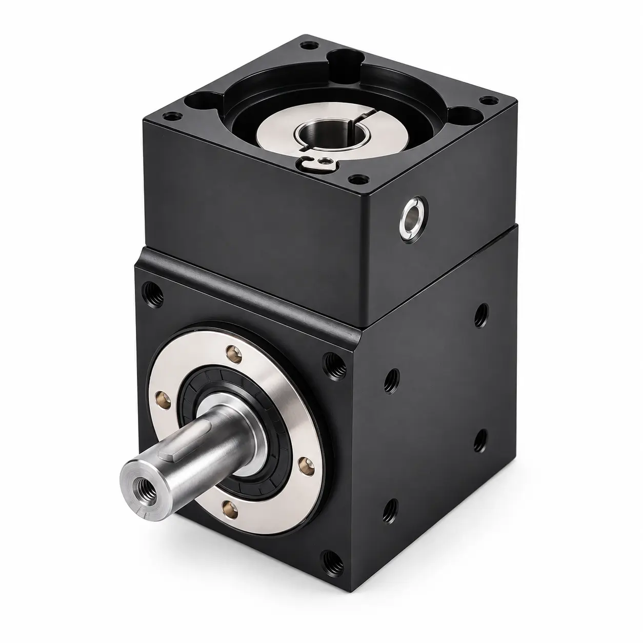
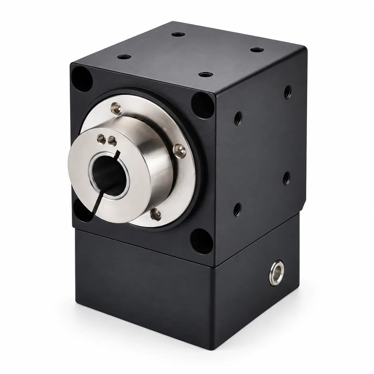
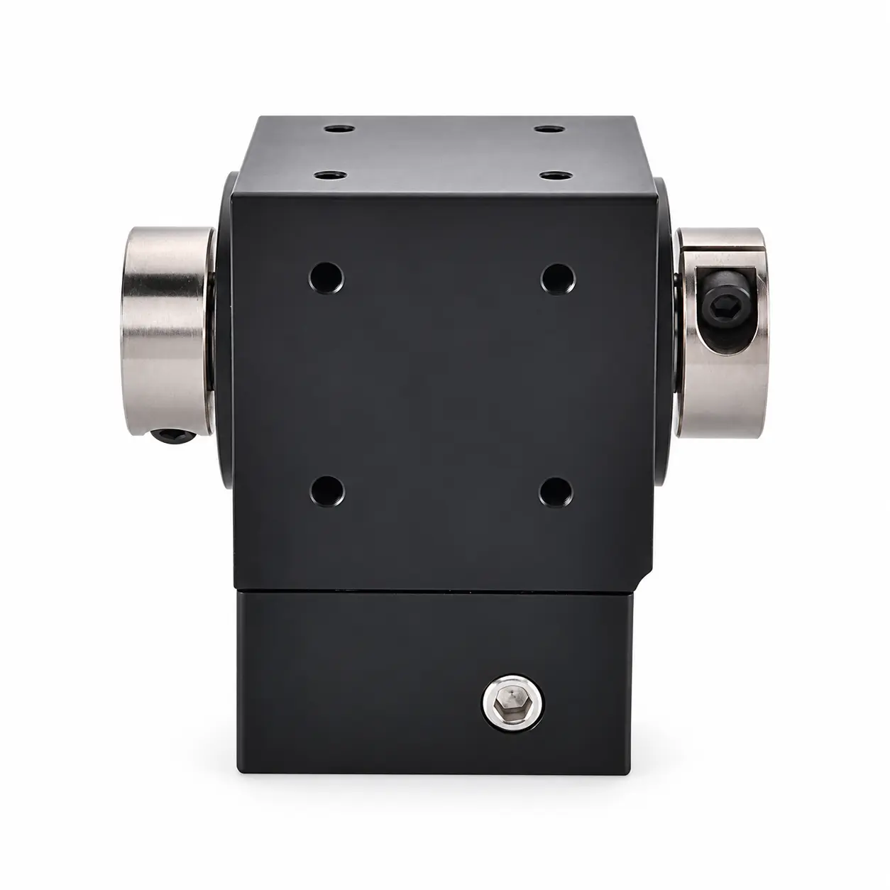
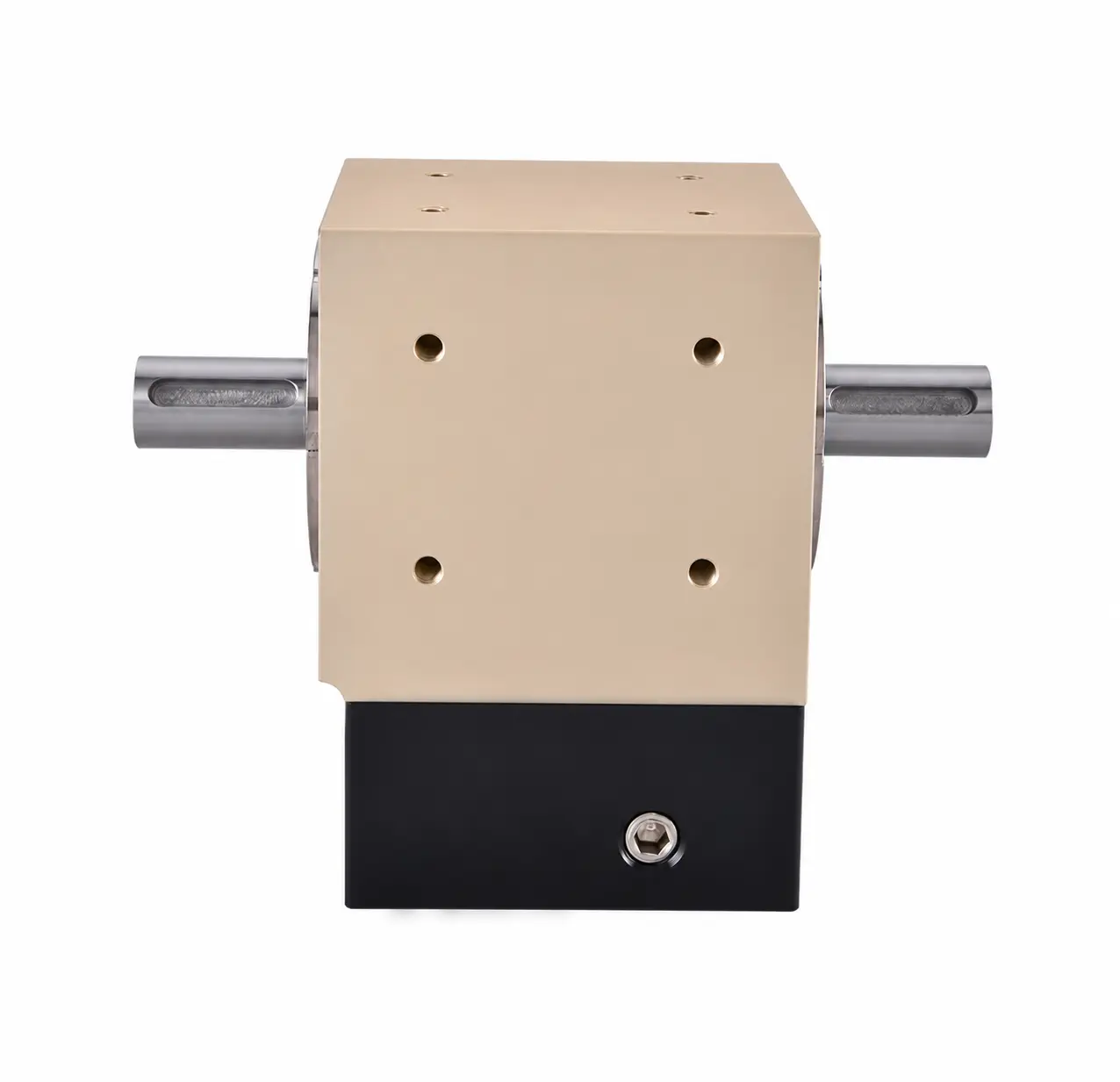
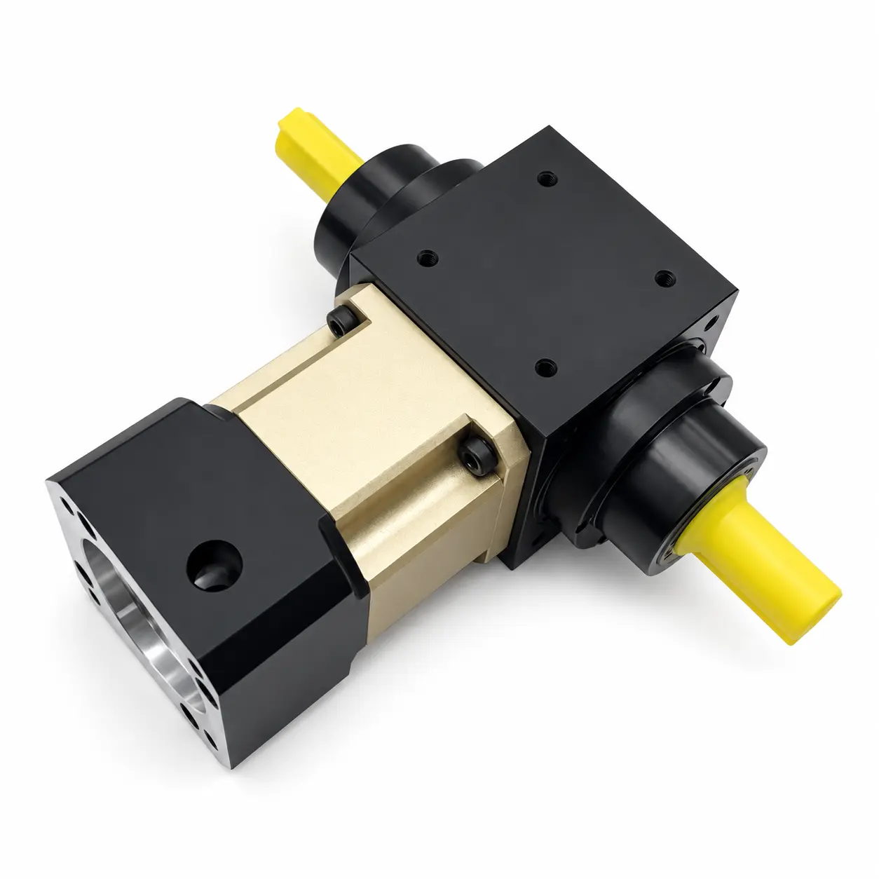
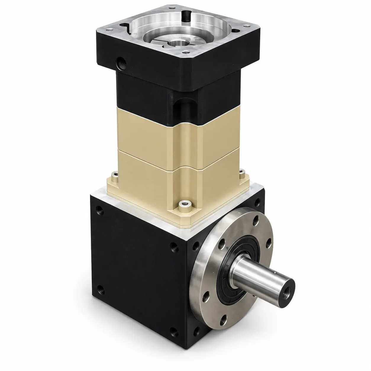
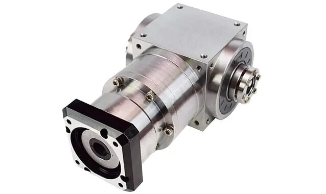
AT-FH Double Keyed-Bore Output Right-Angle Gearboxes
Compare models in this series, check their motor interfaces and find the matching drawings and STEP files.
Model / Specifications
← BackRight Angle Gearbox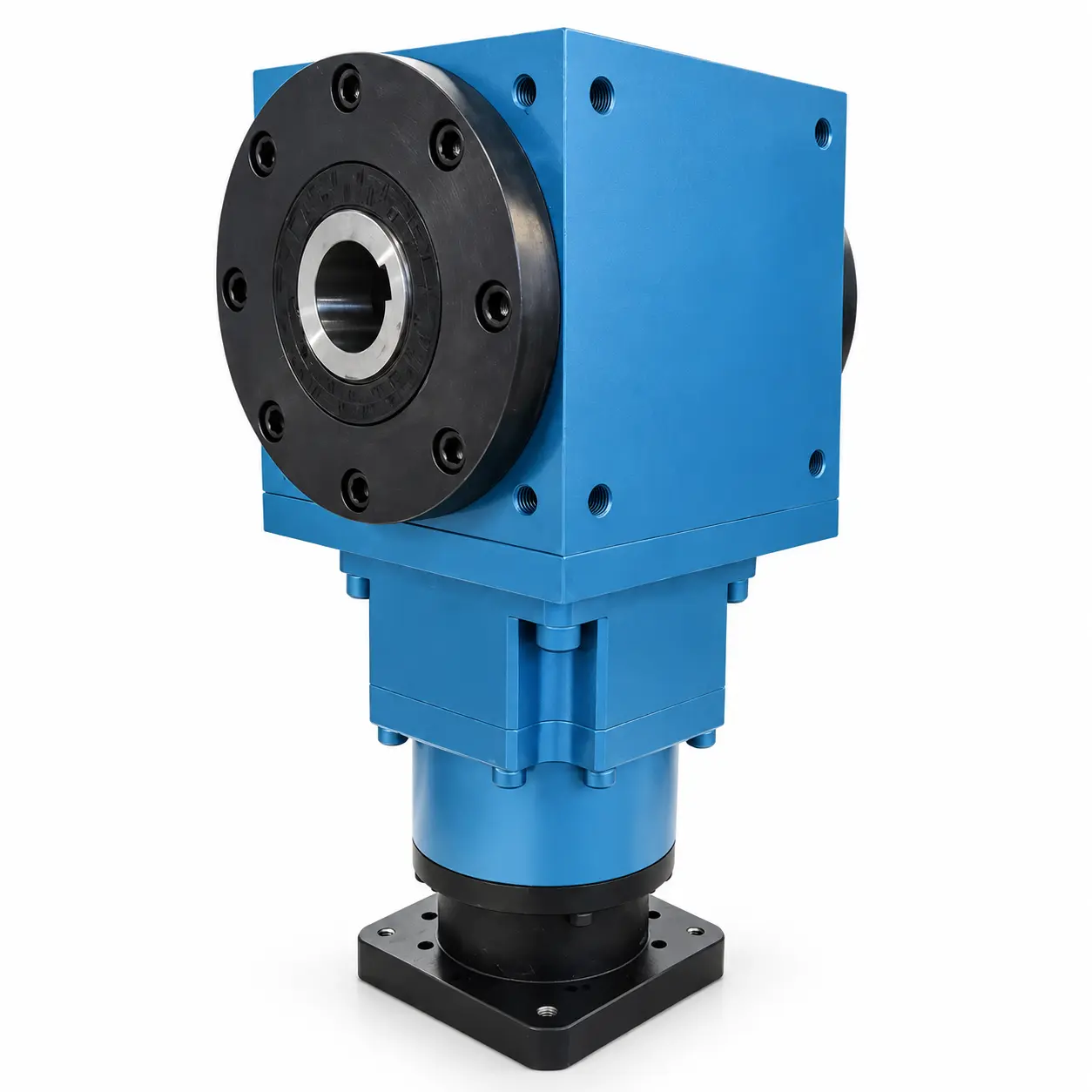
AT060-FH Double Keyed-Bore Output Right-Angle Gearbox
View Specifications & Resources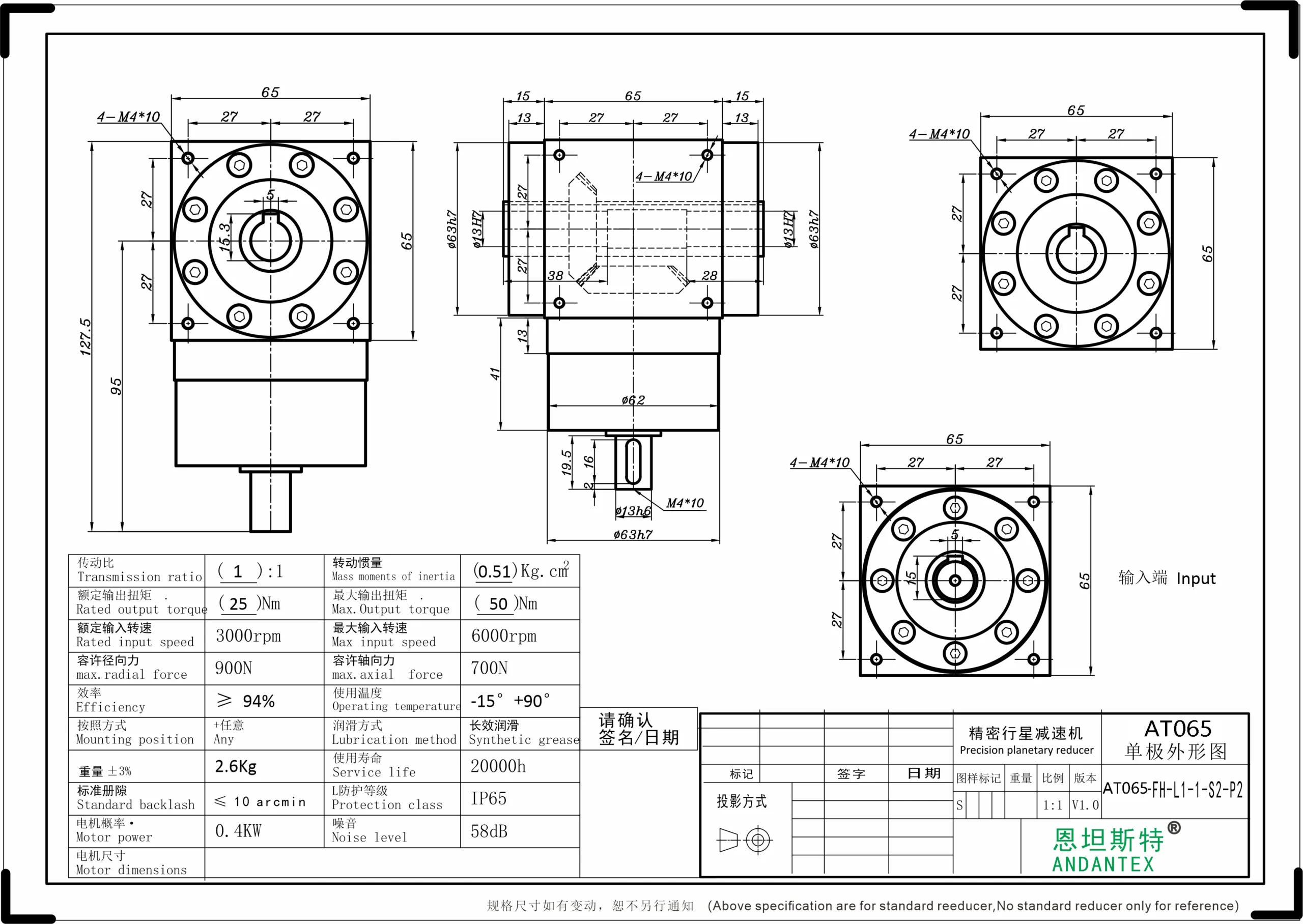
AT065-FH Double Keyed-Bore Output Right-Angle Gearbox
View Specifications & Resources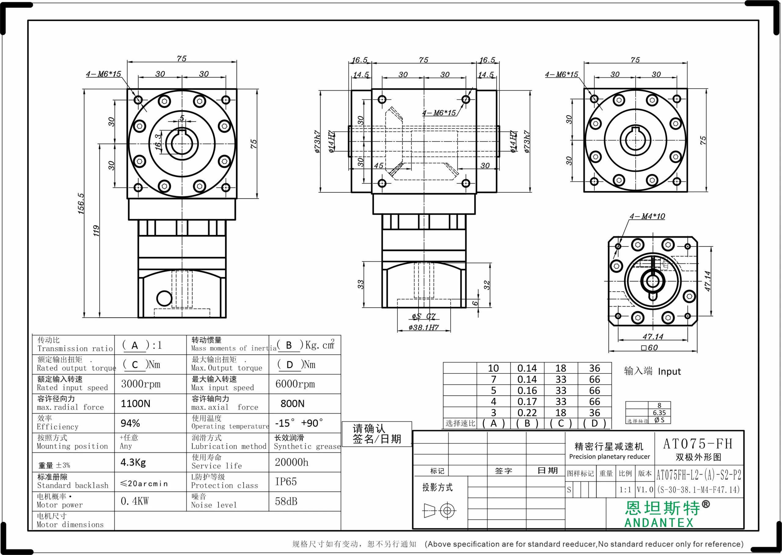
AT075-FH Double Keyed-Bore Output Right-Angle Gearbox
View Specifications & Resources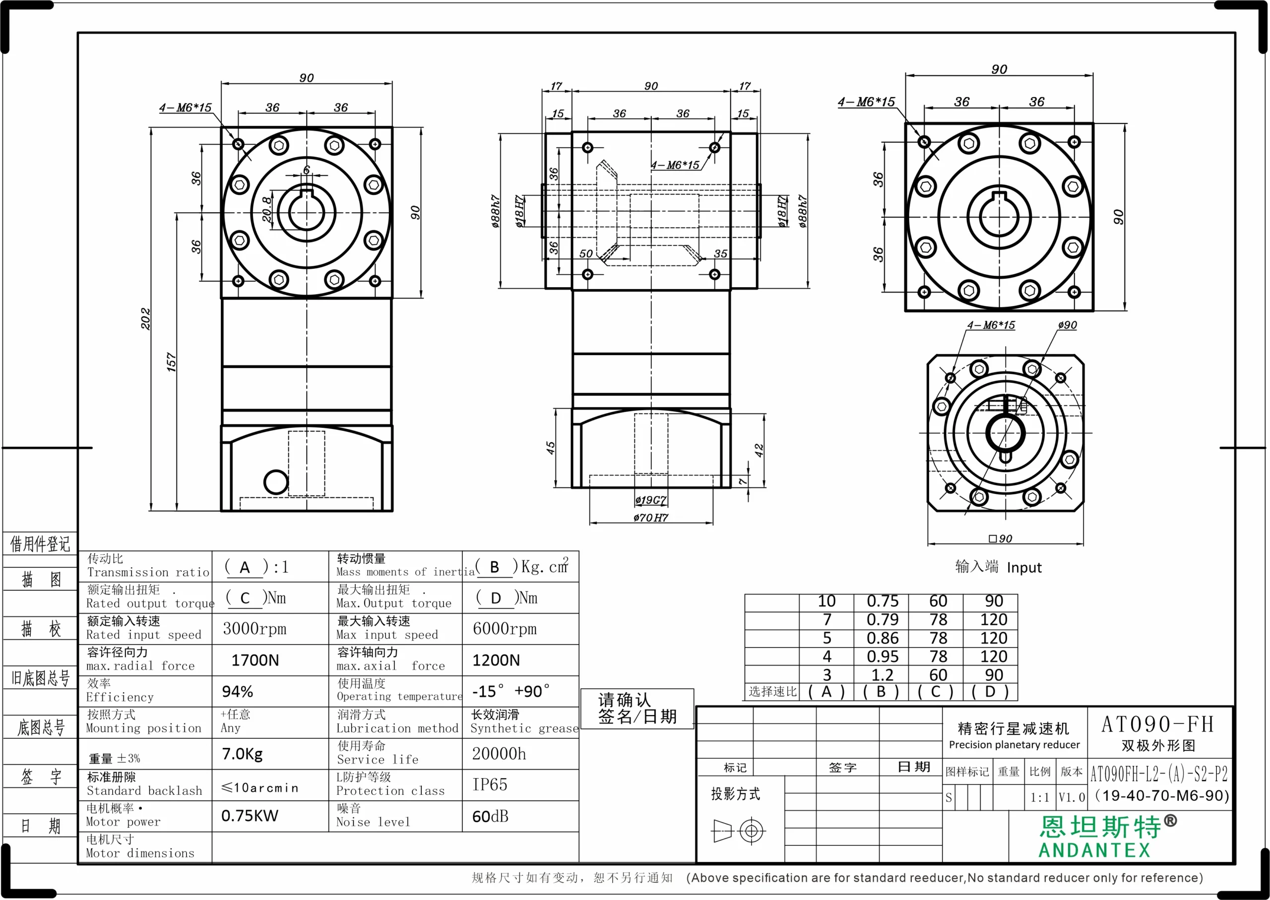
AT090-FH Double Keyed-Bore Output Right-Angle Gearbox
View Specifications & Resources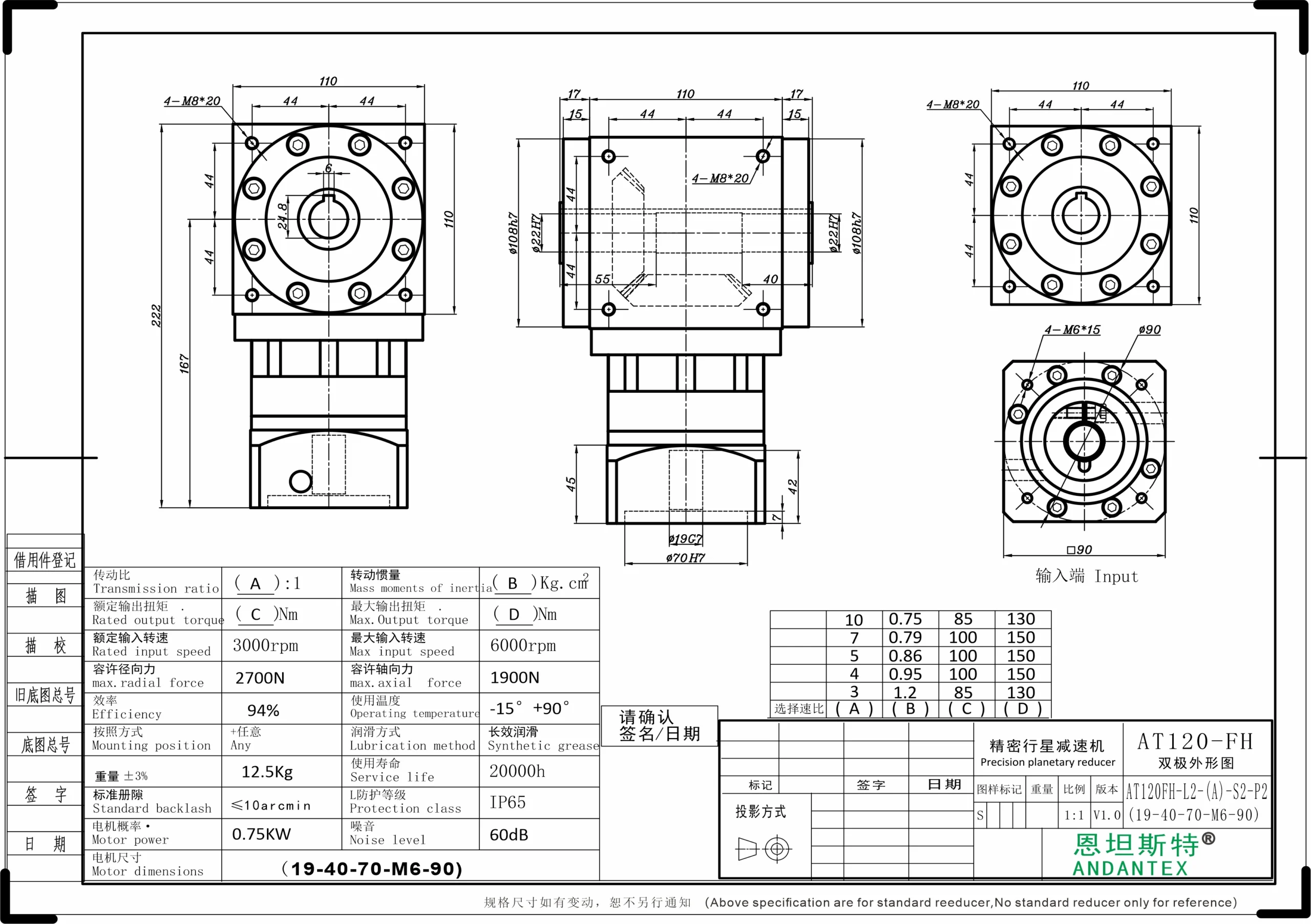
AT120-FH Double Keyed-Bore Output Right-Angle Gearbox
View Specifications & Resources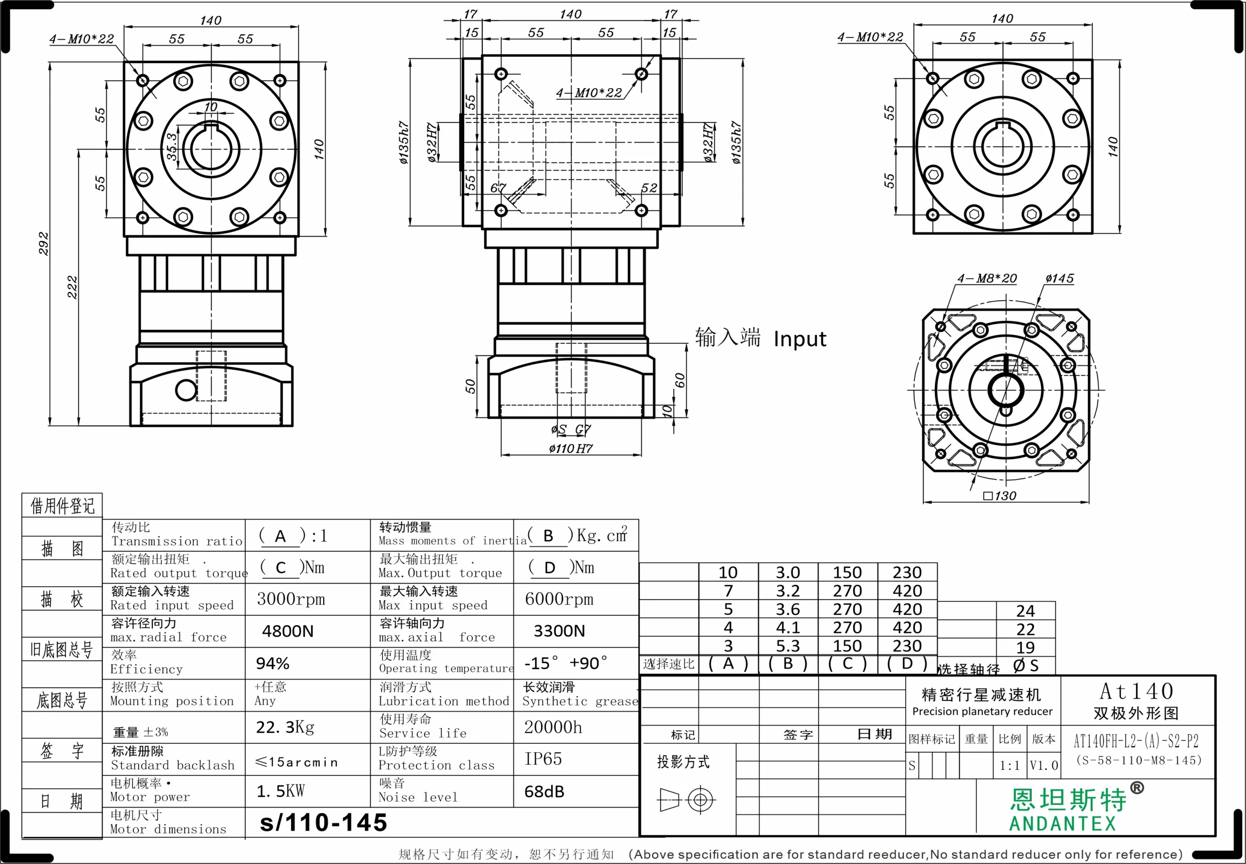
AT140-FH Double Keyed-Bore Output Right-Angle Gearbox
View Specifications & Resources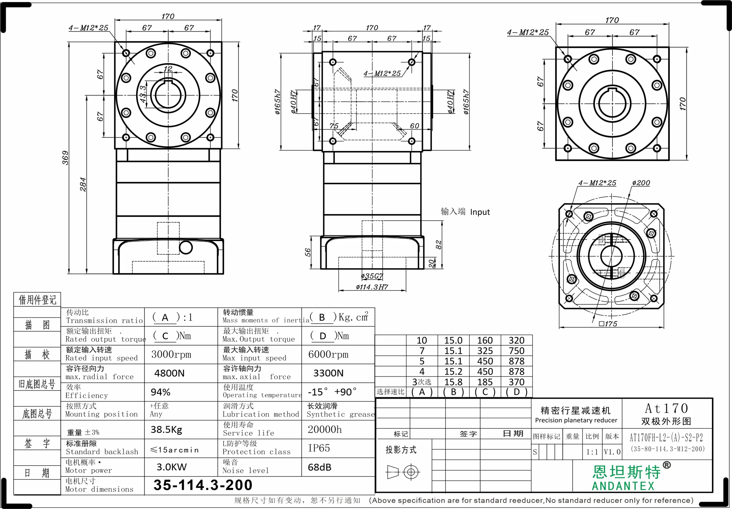
AT170-FH Double Keyed-Bore Output Right-Angle Gearbox
View Specifications & Resources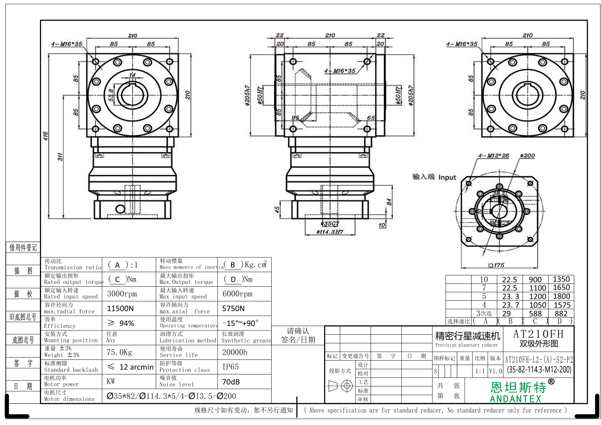
AT210-FH Double Keyed-Bore Output Right-Angle Gearbox
View Specifications & Resources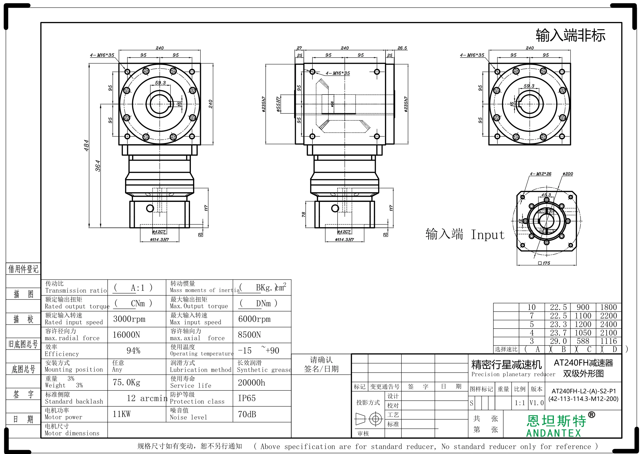
AT240-FH Double Keyed-Bore Output Right-Angle Gearbox
View Specifications & ResourcesSelecting an AT-FH Double Keyed-Bore Output Gearbox
FH uses double keyed-bore outputs. Select the complete model, stage code and input interface for the required right-angle drive layout. The supplied AT065-FH L1 drawing uses a 13 mm keyed input shaft; coupling-bore input variants are identified by their own drawings.
- Match both output bores, keyways, shaft engagement and supporting bearings to the driven mechanism. Check the load on both output connections and obtain the applicable rating basis for the complete configuration.
- For motor matching, verify shaft diameter and length, locating pilot, mounting pitch circle and fasteners. An S input designation can represent several bore options; a fixed-bore STEP covers only its stated variant.
- Use the configuration-specific torque, backlash and force values on the product page. L1, L2, L3 and L4 resources remain separate; L4 is retained as a drawing code.
- For belt, rack, screw or direct-coupled automation axes, provide the motion cycle, operating torque, external forces and installation envelope. Include robot peripheral, lithium-battery, semiconductor or vision-equipment requirements where relevant.
FH keyed-bore outputs differ from FC double-bore outputs with locking rings and FC1 single-bore outputs with a locking ring. Original-size drawings, supplied PDF files and available STEP configurations are listed on each model page. AT060 currently has STEP files only; matching 2D drawings and ratings require confirmation.
Related guidance: compare FC and FC1 locking-ring output configurations.
Request a Model and Drawing Review
Send the full model or series name, motor information, application layout and operating requirements. Include the required interfaces and any performance values that need confirmation.
Send your selection requirements or open the drawing and document center to review available resources.