 PRECISION DRIVE
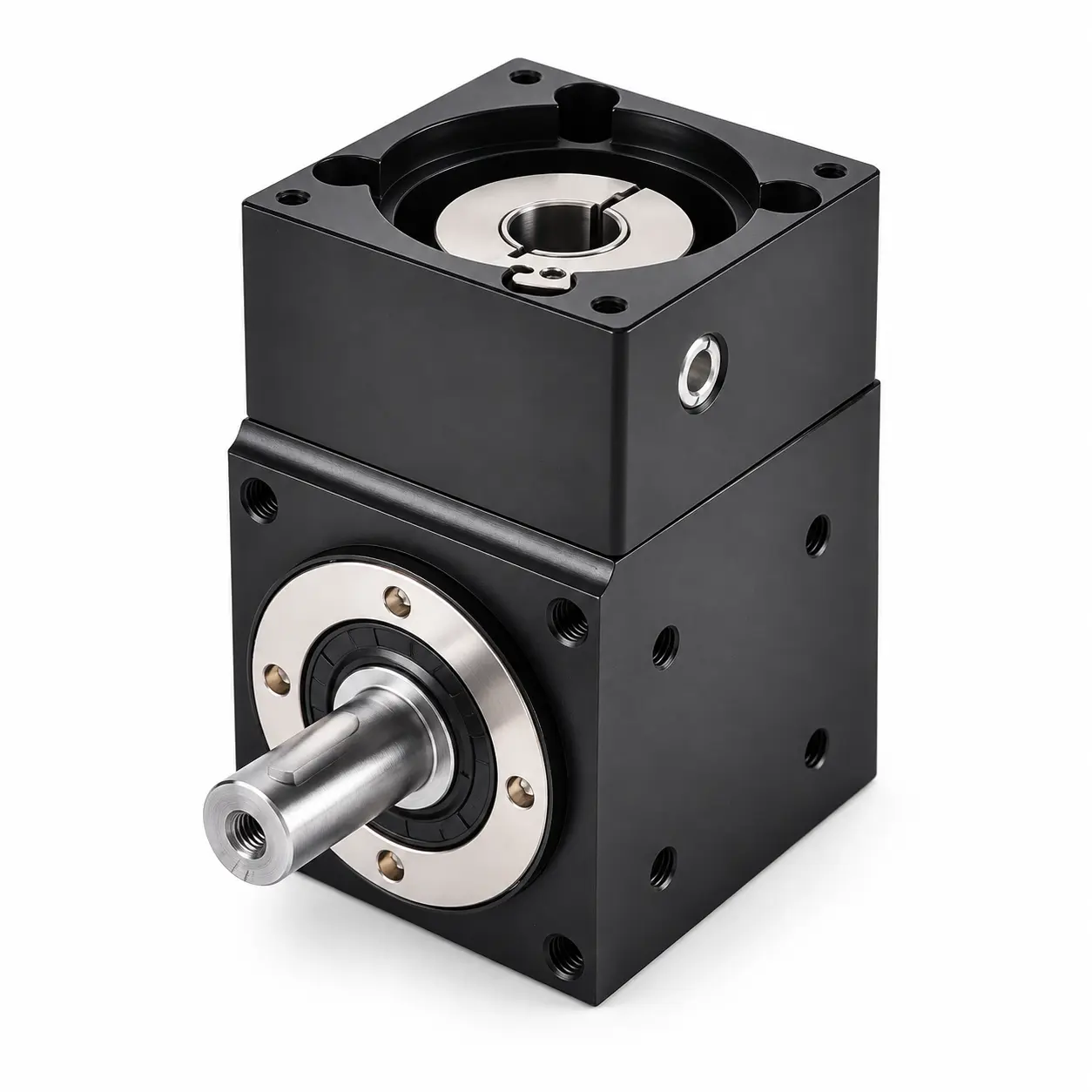
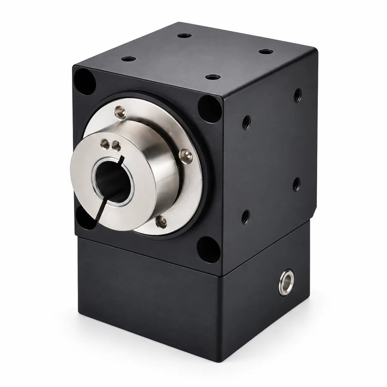
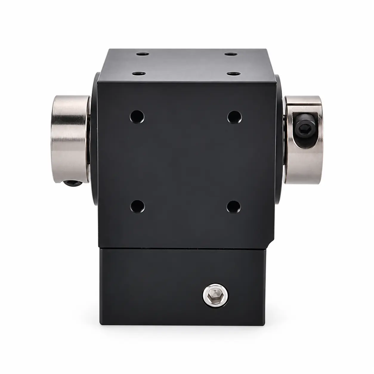
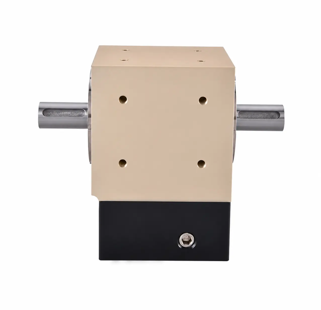
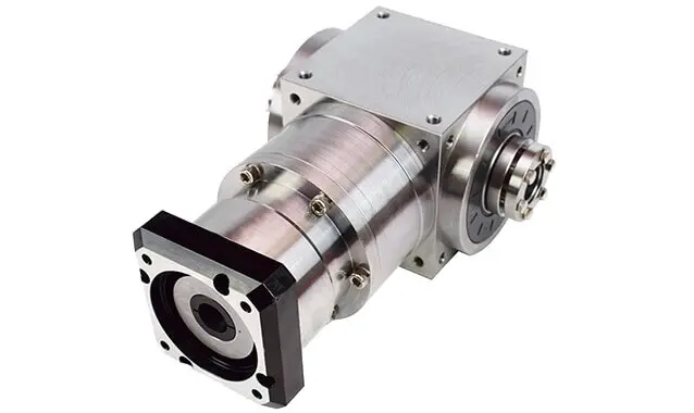
AT-FC & AT-FC1 Gearboxes with Locking Rings
Compare models in this series, check their motor interfaces and find the matching drawings and STEP files.
Model / Specifications
← BackRight Angle Gearbox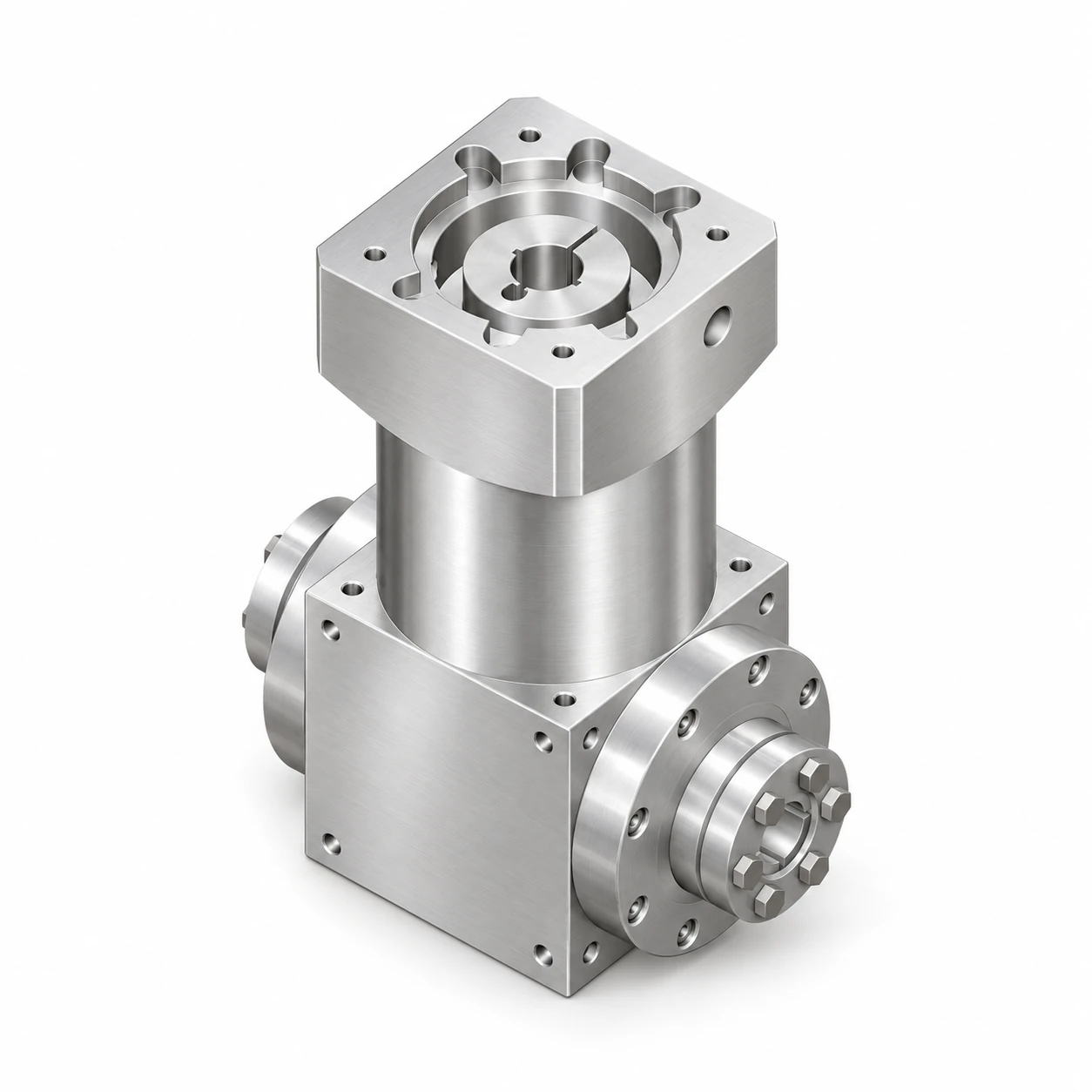
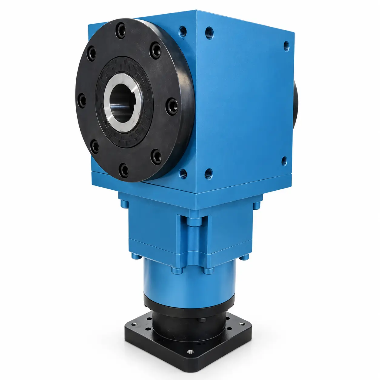
AT090-FC Double-Bore Output Right-Angle Gearbox with Locking Rings
View Specifications & Resources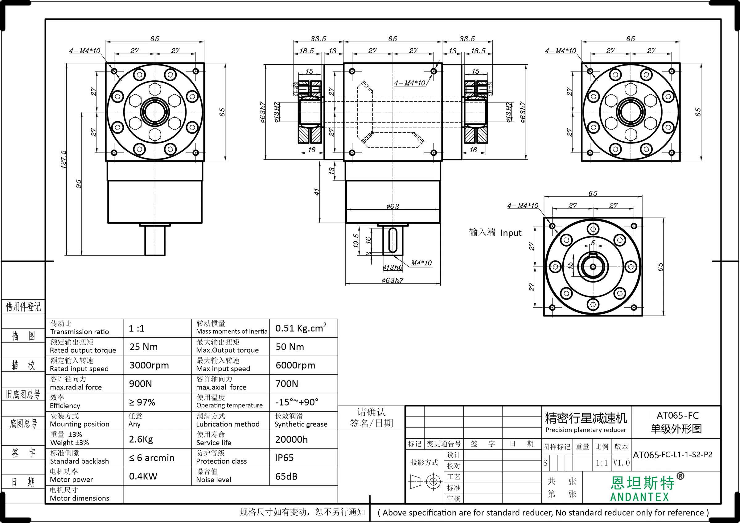
AT065-FC Double-Bore Output Right-Angle Gearbox with Locking Rings
View Specifications & Resources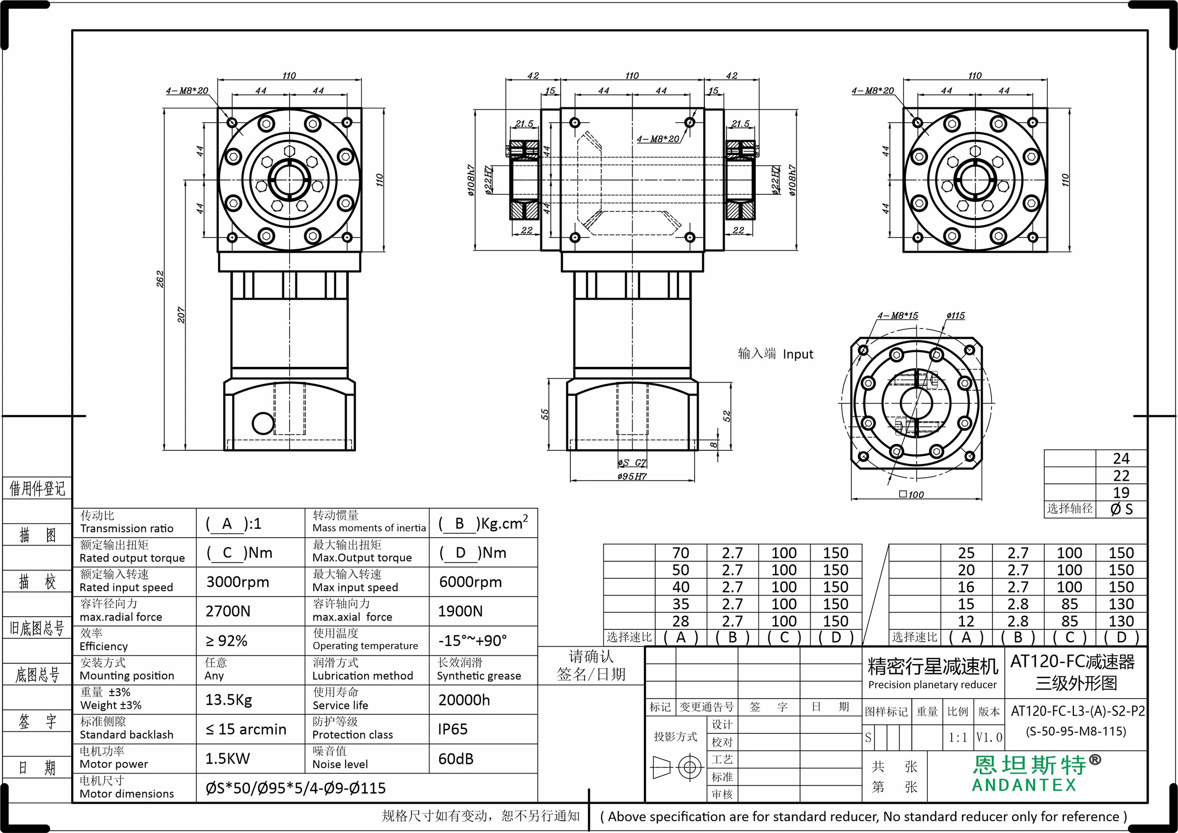
AT120-FC Double-Bore Output Right-Angle Gearbox with Locking Rings
View Specifications & Resources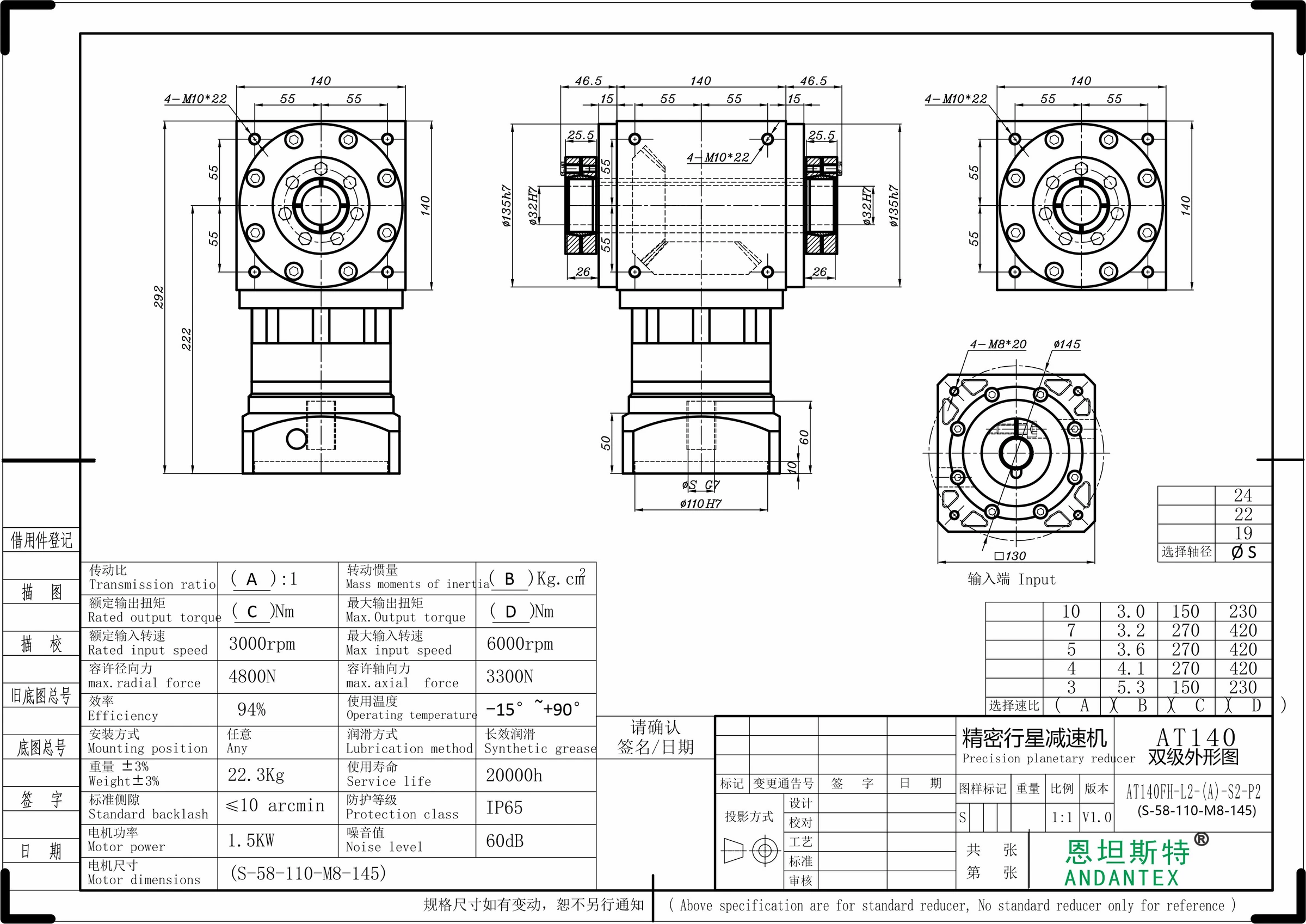
AT140-FC Double-Bore Output Right-Angle Gearbox with Locking Rings
View Specifications & Resources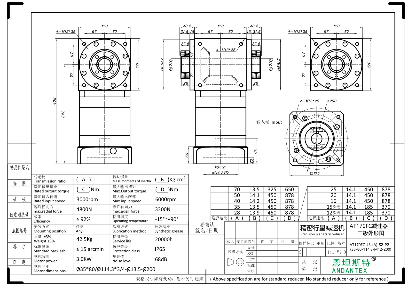
AT170-FC Double-Bore Output Right-Angle Gearbox with Locking Rings
View Specifications & Resources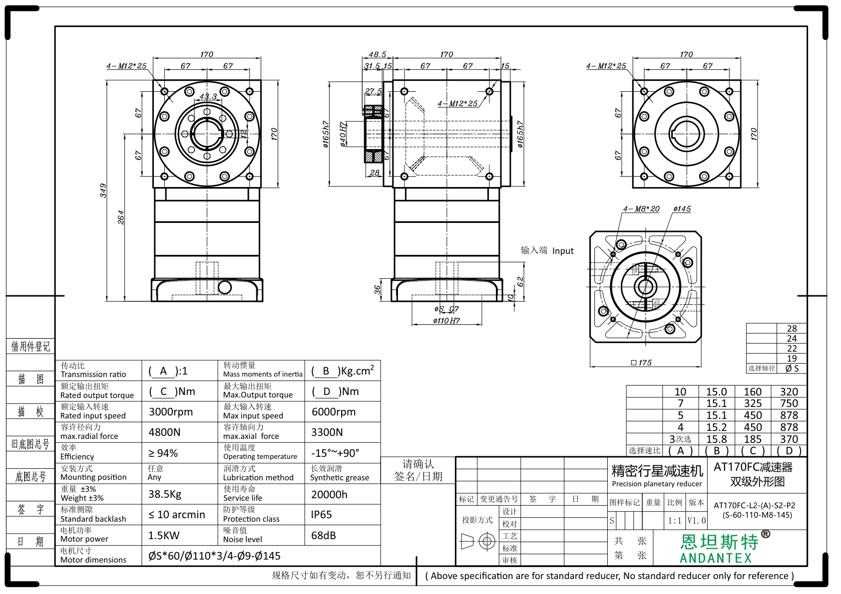
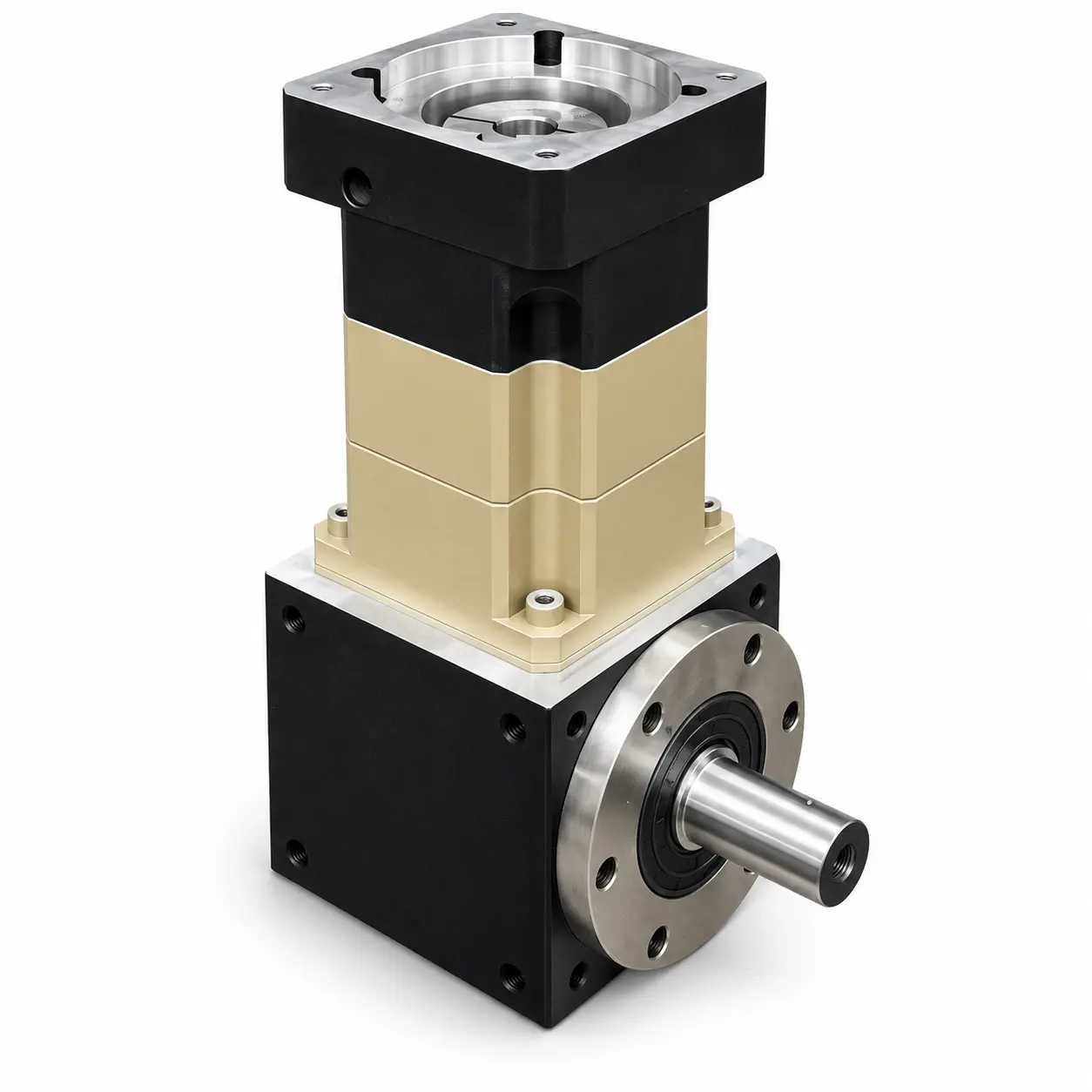
AT170-FC1 Single-Bore Output Right-Angle Gearbox with Locking Ring
View Specifications & ResourcesFC Double-Bore and FC1 Single-Bore Outputs with Locking Rings
FC has double-bore output with locking rings. FC1 has single-bore output with a locking ring. Keep these output structures separate when selecting a model. The AT065-FC L1 drawing in this range uses a 13 mm keyed input shaft; the other published configurations use coupling-bore input for matching a motor shaft.
- Select the complete model, stage and motor interface. AT170-FC and AT170-FC1 have different output structures and must not be treated as interchangeable.
- AT065-FC L1 is the 13 mm keyed-shaft input version with a 1:1 ratio. Keep it in the FC family while clearly identifying its input structure.
- S in a drawing denotes a variable input bore. Where a STEP is supplied for 22 mm input, it represents that specific variant only. Check pilot diameter, mounting pitch circle, thread and shaft engagement against the selected drawing.
- For FC double-bore output, provide the load on each side and confirm the applicable torque rating for the complete configuration. Do not assume that another series uses the same loading limit.
Use each model page for its original dimension drawings and available STEP files. A dimension drawing or representative rendering does not replace verification of the complete order configuration.
Related guidance: motor interface dimensions checklist.
Request a Model and Drawing Review
Send the full model or series name, motor information, application layout and operating requirements. Include the required interfaces and any performance values that need confirmation.
Send your selection requirements or open the drawing and document center to review available resources.