 PRECISION DRIVE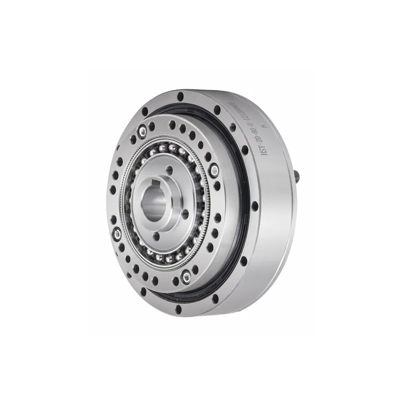
CS8 Harmonic Reducer
Read about CS8. Find related information and resources from ANDANTEX.
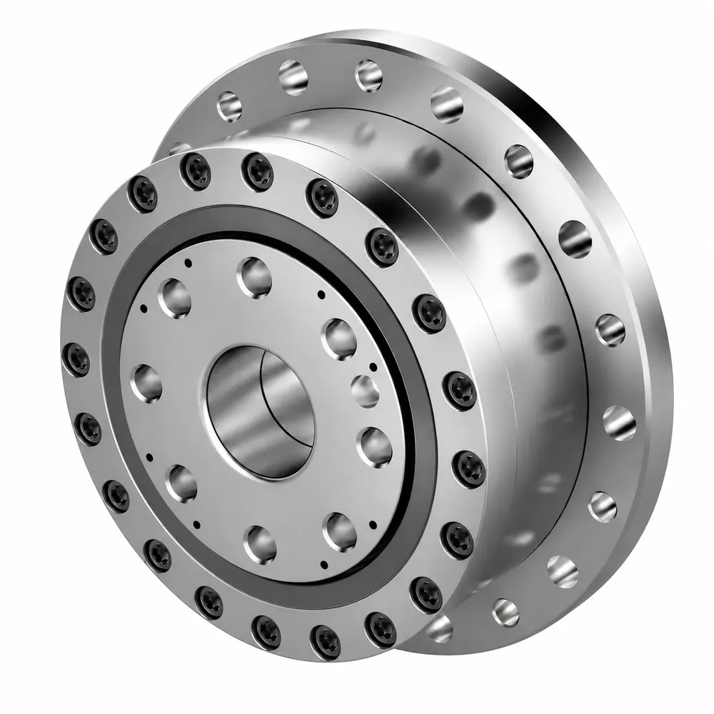
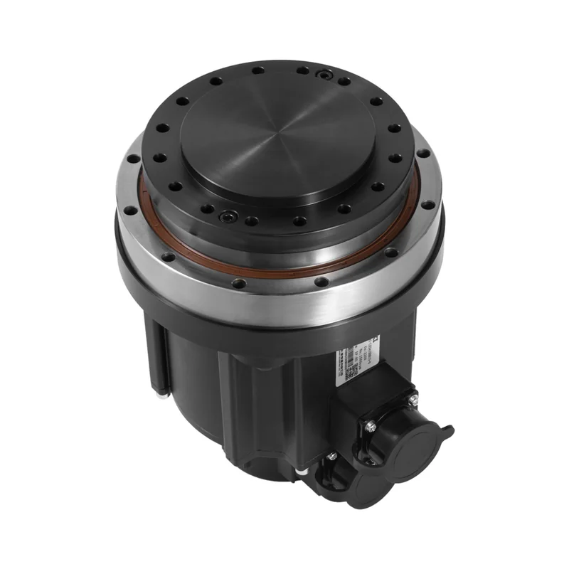
CS8 Harmonic Reducer
Read about CS8. Find related information and resources from ANDANTEX.
Key Technical Specifications
| Item | Parameters | Description |
|---|---|---|
| Product Series | CS General-Purpose Harmonic Reducer | Harmonic Reducer |
| Specifications / Frame Size | 8 | Model Specifications |
| Gear Ratio | 50 / 100 | Torque Varies by Ratio, See the Original 2D Specification Table |
| Rated Output Torque | 1.8–2.4 Nm | Gear Ratio: 50=1.8, 100=2.4 Nm; Drawing Conditions: Input 2000 r/min |
| Maximum Torque | 6.6–9.0 Nm | Drawing Annotation " Maximum Momentary Allowable Torque ", Not a Continuous Operating Rating |
| Backlash | ≤40 arcsec | The Original Unit Is Arcseconds, Do Not Confuse with Arcminutes Used for Planetary Gearboxes |
| Maximum Input Speed | 8500 rpm | Maximum Allowable Input Speed Specified in the Drawing ( Grease Lubrication) |
| Allowable Average Input Speed | 3500 rpm | This Is the Allowable Average Input Speed ( Grease Lubrication), Not the Rated Output Speed |
| Weight | 0.08 kg | Component Weight Listed in the Drawing; Check Other Combinations against the Actual Configuration |
| Service Life | 10000 h | All Listed Ratios: Drawing Annotation 10000 h |
Unlisted Specifications Are Pending, Confirm for the Specific Configuration.
Specifications / Gear Ratio
50 / 100
Torque Varies by Ratio, See the Original 2D Specification Table
Gear Ratio, Confirm Stages & Interface Using the Required Configuration and Official Drawing.
CS8 Mounting Interface Verification
For Harmonic Reducers, Verify the Wave Generator-to-Motor Connection, Output Hole Locations & Housing Pilot Dimensions.
First Check This Model’s Published 2D Resources; For Other Structures or Connection Options, Search the Website Interface Library by Dimensions.
CS8 2D / 3D Engineering Resources
Each Standard Size, Motor Interface & Custom Combination Is Managed Separately 2D Drawing and 3D STEP; 2D Supports Images and PDF.
Check the Model before Downloading, Size & Interface
Use the Current Order Model & Official Engineering Drawing; Custom Input, Outputs & Flanges Require Their Own Resources.
PACKAGING & DELIVERYPackaging & DeliveryView Packaging Images & Delivery Notes
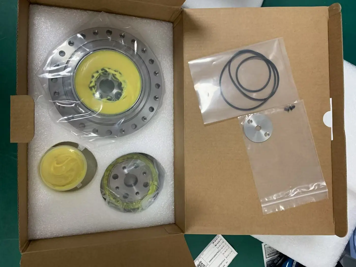
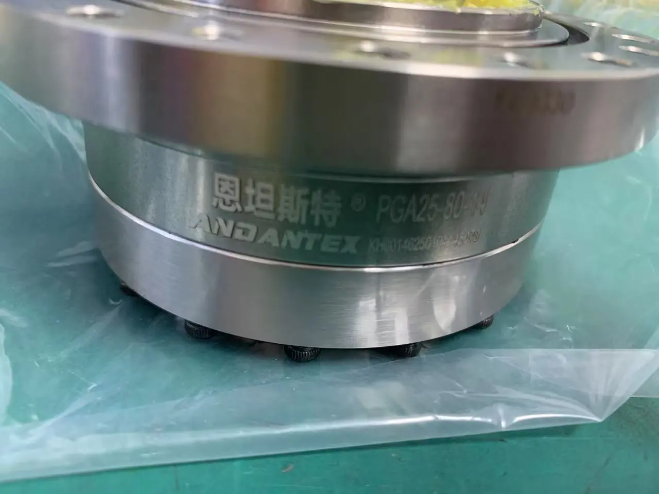
Packaging Images Are for Reference, Actual Packaging, Labels & Accessories Depend on the Confirmed Model & Order.
Application Verification
Provide the Load, Target Output Speed, Start/Stop Cycle, Installation Space & Operating Environment, Confirm Whether This Model Is Suitable.
View ApplicationsFAQ
How to Verify the Motor Interface?
Check Motor Shaft Diameter, Shaft Length, Keyway, Pilot Diameter & Mounting Hole Locations, Use the Official Drawing for the Matching Configuration.
What If Specifications or Drawings Are Unavailable?
Submit the Model & Required Configuration for Engineering Review, Unpublished resources do not mean the configuration has been verified.
Need a Quote or Engineering Review?
Submit CS8 Gear Ratio for, Load & Installation Requirements.