 PRECISION DRIVE
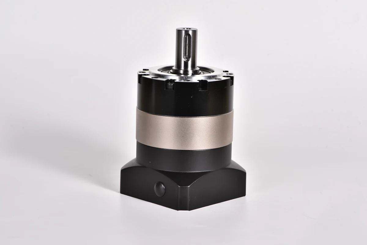
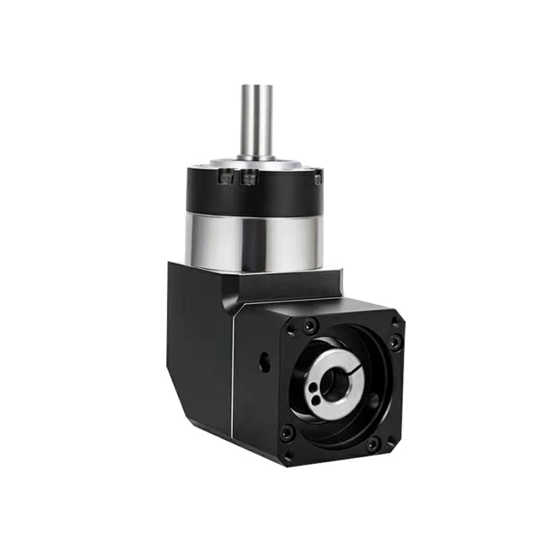
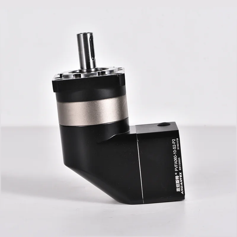
A hollow rotary table combines a large central opening with a rigid rotary output. The opening can route cables, air lines, vacuum tubes, optical fibers or inspection paths through the axis, while the table supports a fixture, camera, dial plate or workpiece.
Start with the load, not the motor wattage
Record the workpiece and fixture mass, table diameter, center-of-gravity offset, target indexing time, angular travel and stops per minute. Motor power is only an initial reference. The mechanism must be sized from torque, inertia, moment load, duty cycle and required positioning performance.
Calculate the required acceleration torque
The total demand includes friction torque and acceleration torque. For a first estimate, calculate the combined rotational inertia of the workpiece, fixture and driven table, then multiply it by angular acceleration. Add friction and process torque, and apply an engineering safety factor appropriate to the duty and load uncertainty.
Required torque ≈ inertia × angular acceleration + friction torque + process torque. This estimate must be checked against the rated and allowable acceleration torque of the exact rotary table and motor combination. Emergency stops and impacts require a separate check.
Check moment load and rigidity
A load that is not centered creates an overturning moment even when its total mass appears modest. Specify the radial offset and vertical height of the center of gravity. Compare the calculated moment with the permissible moment load, axial load and radial load for the selected model. Larger diameter fixtures can also increase inertia sharply.
Select the ratio from speed and cycle time
Use the required table speed and available motor speed to establish a practical ratio. A higher ratio can increase available output torque and reduce the load inertia reflected to the motor, but it also changes maximum table speed and cycle time. Verify acceleration, dwell and settling time for the complete cycle rather than using only steady-state speed.
Choose the appropriate ANDANTEX configuration
| Series | Arrangement | Typical selection question |
|---|---|---|
| NT | Standard hollow rotary table | Does the application need a conventional motor arrangement and a large through-hole? |
| NTF | Combined hollow rotary table | Does the equipment layout require the NTF mounting configuration? |
| NTFA | Right-angle hollow rotary table | Must the motor fit beside the axis in a short installation envelope? |
Series names do not replace model-level verification. Confirm the exact drawing, ratio, motor interface, rated torque, permissible loads and accuracy class before ordering.
Installation checklist
- Use a flat, rigid mounting surface and the specified fasteners.
- Keep cable and hose bend radii within their limits through the full rotation.
- Prevent the routed cable bundle from rubbing the inner bore or applying torsion to connectors.
- Check horizontal or vertical mounting against the exact model specification.
- Protect the unit from dust, coolant, humidity and temperature outside its rated conditions.
- After installation, test low-speed motion, direction, homing, runout and cable movement before full-cycle operation.
Information needed for model selection
Send the motor model, workpiece and fixture mass, turntable diameter, center-of-gravity offset, angle per move, indexing time, stops per minute, mounting orientation and required repeatability. A sketch or 3D layout helps verify the central opening and motor clearance.
Browse the ANDANTEX hollow rotary table range, review the vision inspection turntable application, or request a model recommendation.
Leave a Technical Question