 PRECISION DRIVE
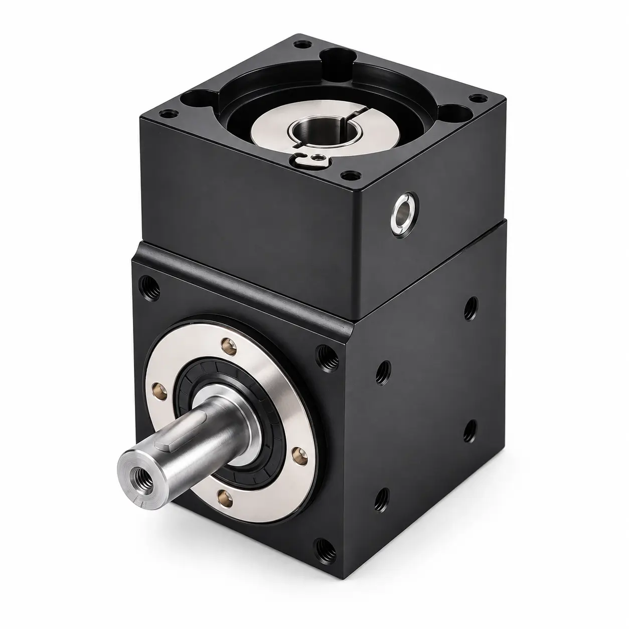
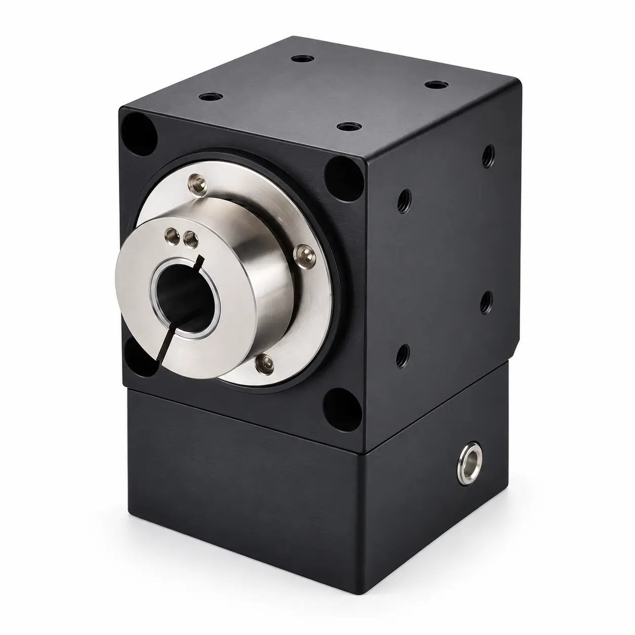
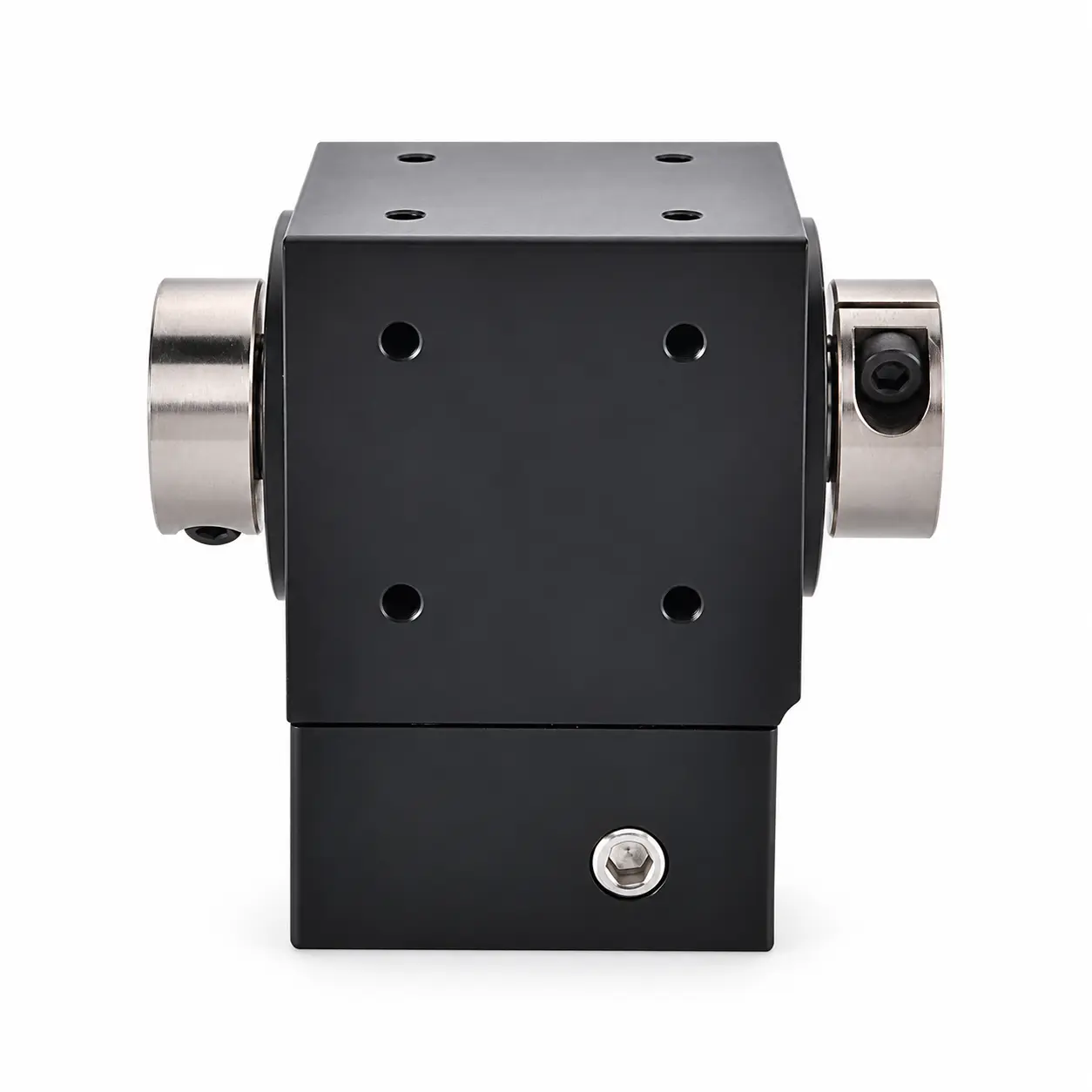
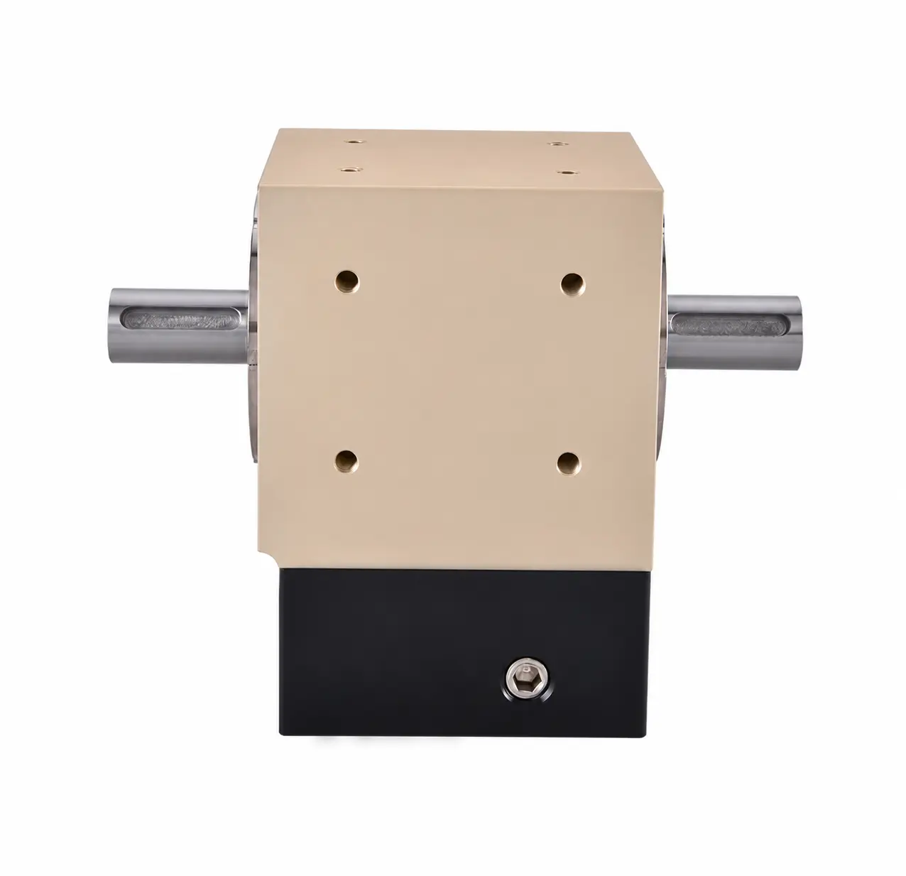
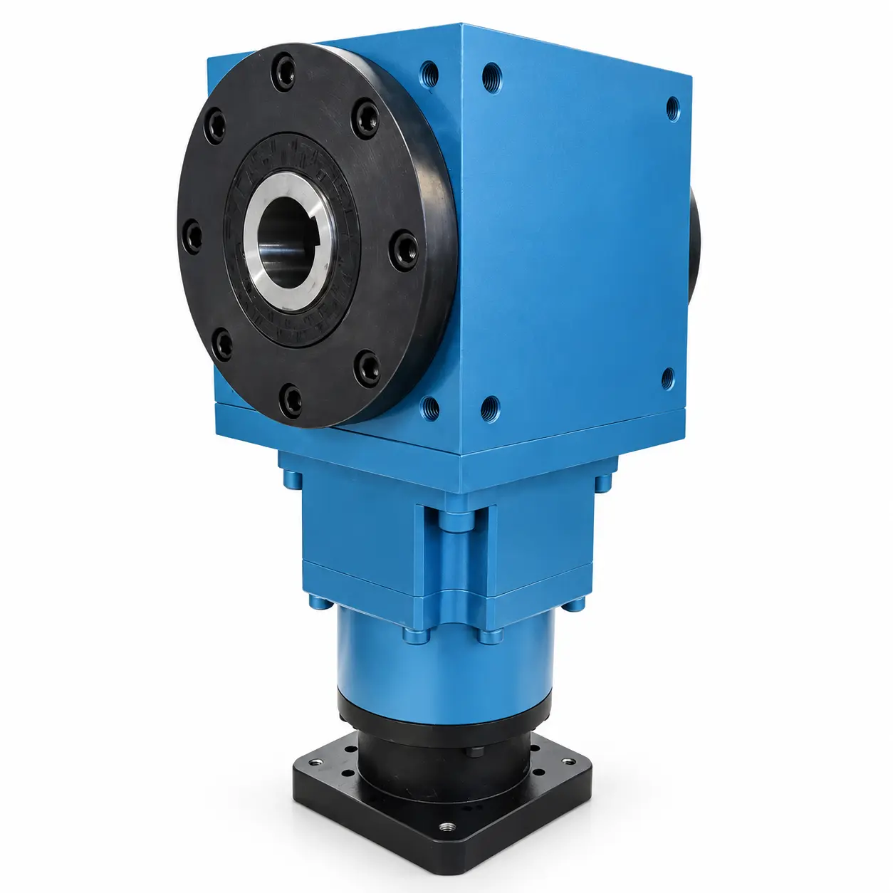
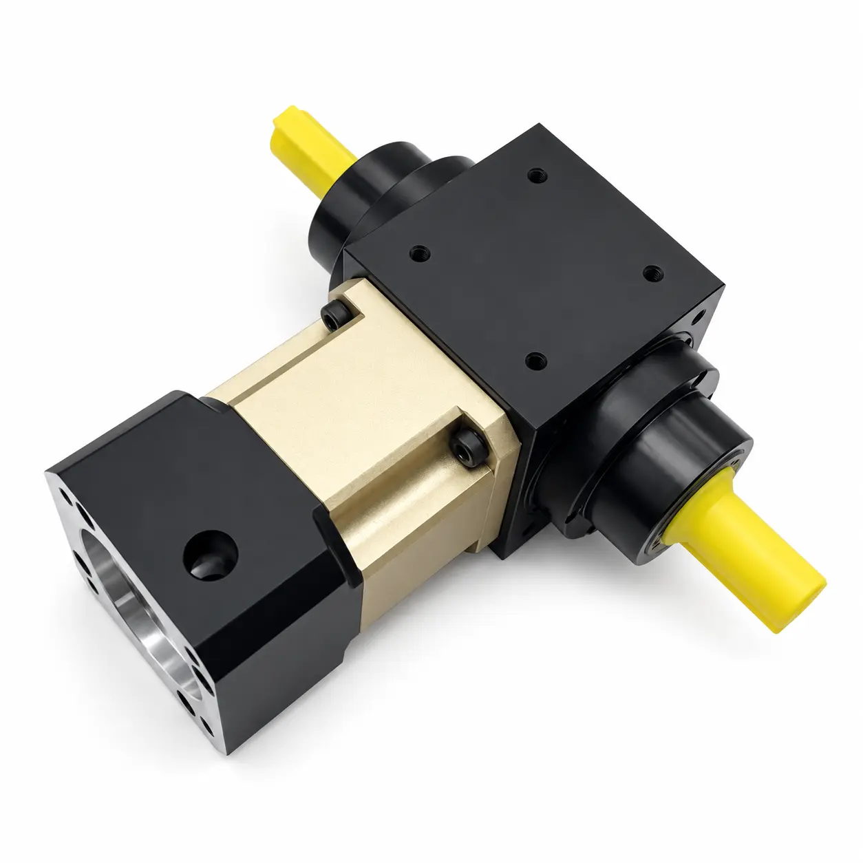
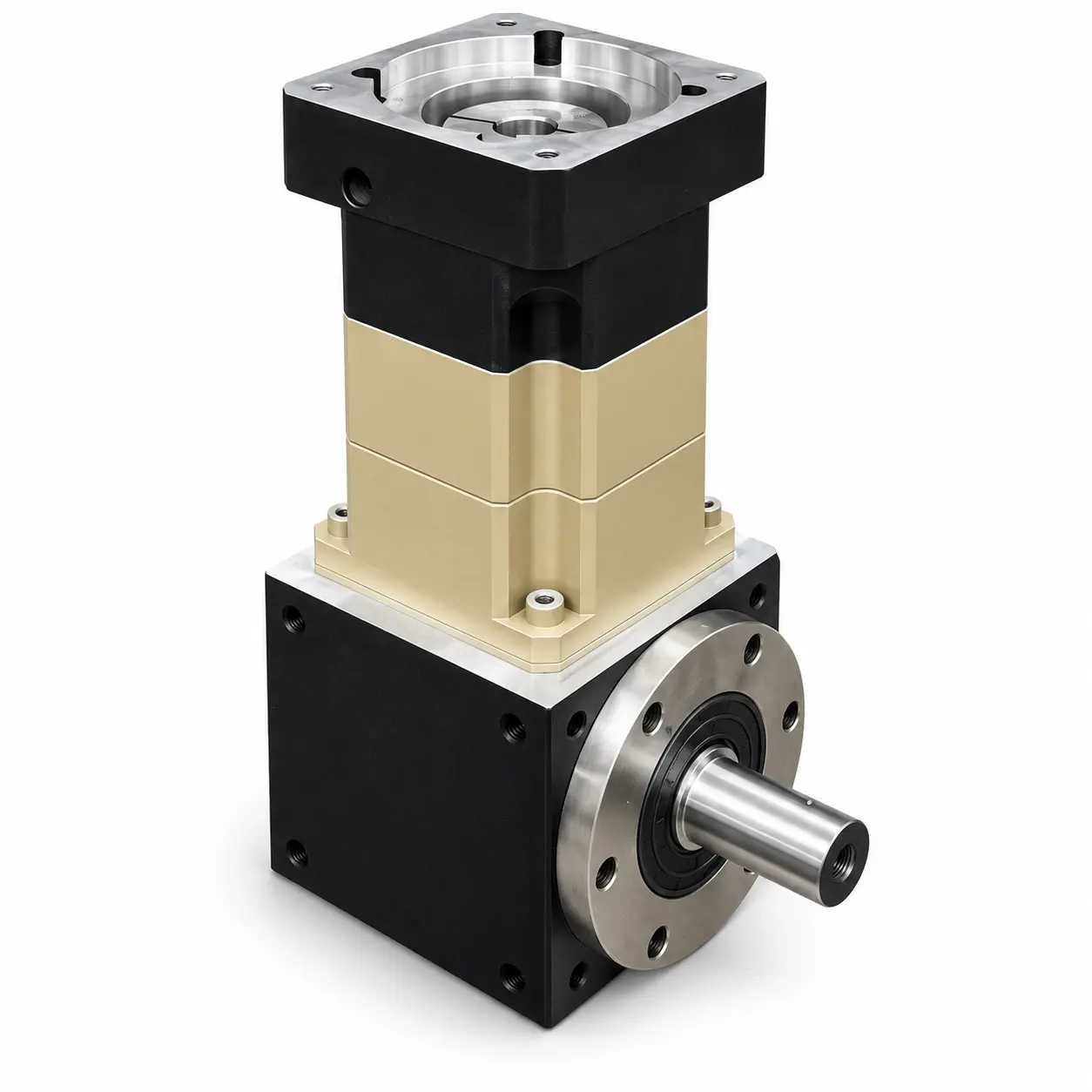
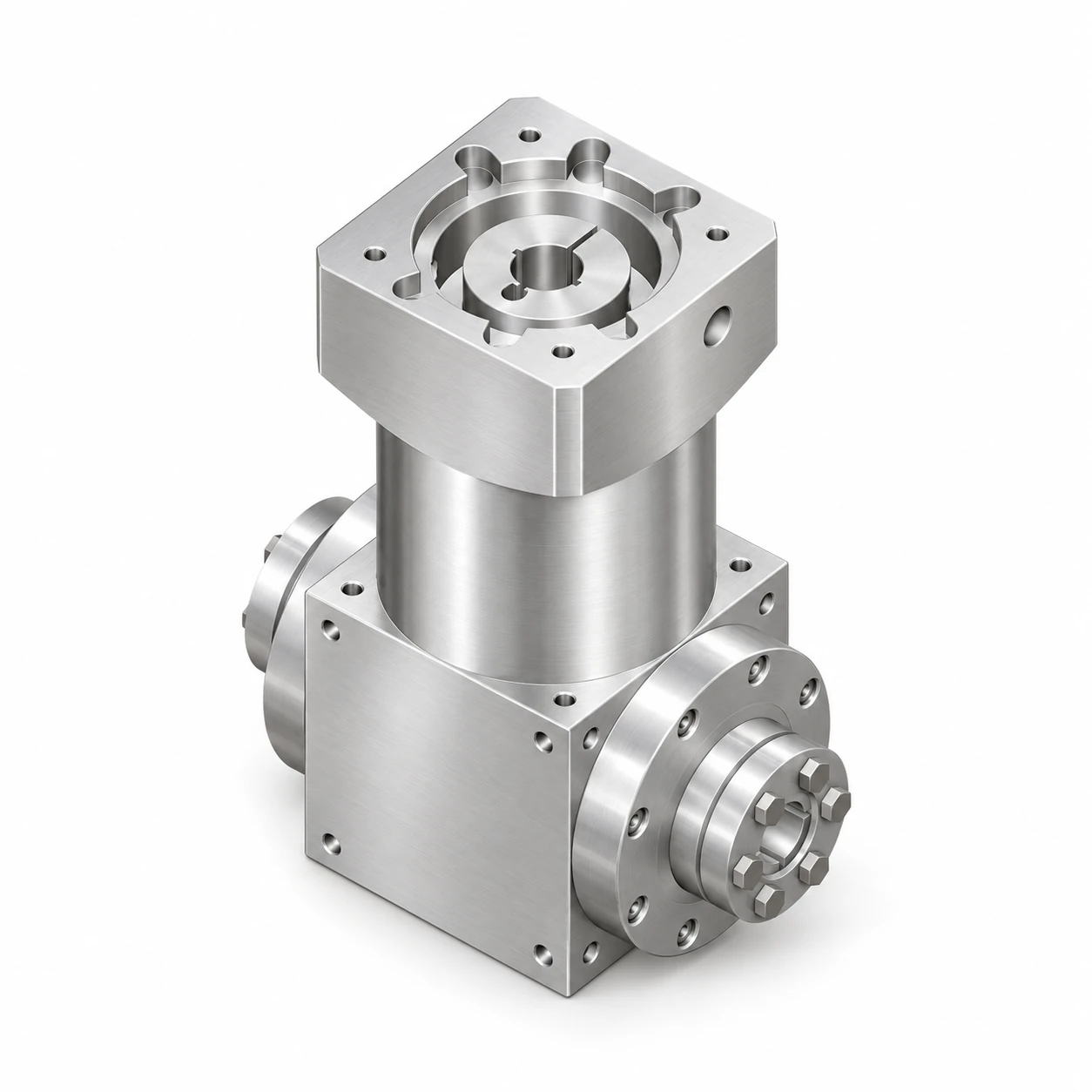
AT090-FL Dual-Shaft Output Right-Angle Gearbox
AT090-FL is a dual-shaft output right-angle gearbox for automation drive layouts requiring two opposed keyed outputs.
The L1, 1:1 reference drawing specifies 18 mm output shafts and 78 Nm rated output torque. L1 uses a keyed shaft input; supplied multi-stage variants use motor-bore input interfaces. The main image is a CAD rendering of one supplied L2 configuration. Compare the stage, ratio, shaft diameter, pilot and mounting pattern in the matching drawing before ordering. Send your motor dimensions, load and duty cycle for selection support and a quotation.
Key Technical Specifications
| Item | Parameters | Description |
|---|---|---|
| Product Series | AT-FL Hollow Input with Dual Shaft Outputs | Right Angle Gearbox |
| Specifications / Frame Size | 090 | Model Specifications |
| Output Structure / Flange Type | Two opposed keyed output shafts, at 90 degrees to the input | FL dual-shaft output configuration. L1 has a keyed shaft input; motor-bore input interfaces are provided for the listed multi-stage variants. |
| Gear Ratio | 1:1 (L1 reference) | L1, 1:1 reference drawing only. Other stages and ratios have different ratings; use the selected configuration drawing. |
| Rated Output Torque | 78 Nm | L1, 1:1 reference drawing only. Other stages and ratios have different ratings; use the selected configuration drawing. |
| Maximum Torque | 120 Nm | L1, 1:1 reference drawing only. Other stages and ratios have different ratings; use the selected configuration drawing. |
| Backlash | ≤6 arcmin | L1, 1:1 reference drawing only. Other stages and ratios have different ratings; use the selected configuration drawing. |
| Maximum Input Speed | 6000 rpm | L1, 1:1 reference drawing only. Other stages and ratios have different ratings; use the selected configuration drawing. |
| Rated Speed | 3000 rpm input | L1, 1:1 reference drawing only. Other stages and ratios have different ratings; use the selected configuration drawing. |
| Efficiency | ≥97% | L1, 1:1 reference drawing only. Other stages and ratios have different ratings; use the selected configuration drawing. |
| Operating Temperature | -15 to +90 °C | L1, 1:1 reference drawing only. Other stages and ratios have different ratings; use the selected configuration drawing. |
| Maximum Axial Force | 1200 N | L1, 1:1 reference drawing only. Other stages and ratios have different ratings; use the selected configuration drawing. |
| Maximum Radial Force | 1700 N | L1, 1:1 reference drawing only. Other stages and ratios have different ratings; use the selected configuration drawing. |
| Weight | 6.5 kg ±3% | L1, 1:1 reference drawing only. Other stages and ratios have different ratings; use the selected configuration drawing. |
| Typical Interface | L1 keyed input Ø18 h6; pilot Ø88 h7; dual output shafts Ø18 h6 | L1, 1:1 reference drawing only. Other stages and ratios have different ratings; use the selected configuration drawing. |
| IP Rating | IP65 | L1, 1:1 reference drawing only. Other stages and ratios have different ratings; use the selected configuration drawing. |
| Service Life | 20,000 h | L1, 1:1 reference drawing only. Other stages and ratios have different ratings; use the selected configuration drawing. |
Unlisted Specifications Are Pending, Confirm for the Specific Configuration.
Find by Interface Dimensions AT090-FL Drawings
Choose the motor interface and reduction stage that match your configuration. Each drawing and STEP file applies to its stated variant.
Enter Motor Shaft Diameter, Pilot Diameter & Mounting Hole Spacing, Find identical or similar input interfaces across recorded models; Resources Requiring Review Are Clearly Marked.
Match Using Dimensions on the Motor Drawing
Filter by motor type, reduction stage and the dimensions on your motor drawing. Matching configurations show their available drawings and STEP files; missing files are marked.
AT090-FL 2D / 3D Engineering Resources
Choose the files for the exact model, motor interface and reduction stage. Dimensional drawings may be images or PDF; 3D models are STEP files.
Check the Model before Downloading, Size & Interface
Check the complete model and configuration against the approved engineering drawing. Custom inputs, outputs and flanges require their own matching files.
Application Verification
Provide the Load, Target Output Speed, Start/Stop Cycle, Installation Space & Operating Environment, Confirm Whether This Model Is Suitable.
View ApplicationsFAQ
How to Verify the Motor Interface?
Check Motor Shaft Diameter, Shaft Length, Keyway, Pilot Diameter & Mounting Hole Locations, Use the Official Drawing for the Matching Configuration.
What If Specifications or Drawings Are Unavailable?
Submit the Model & Required Configuration for Engineering Review, Unpublished resources do not mean the configuration has been verified.
Need a Quote or Engineering Review?
Submit AT090-FL Gear Ratio for, Load & Installation Requirements.