 PRECISION DRIVE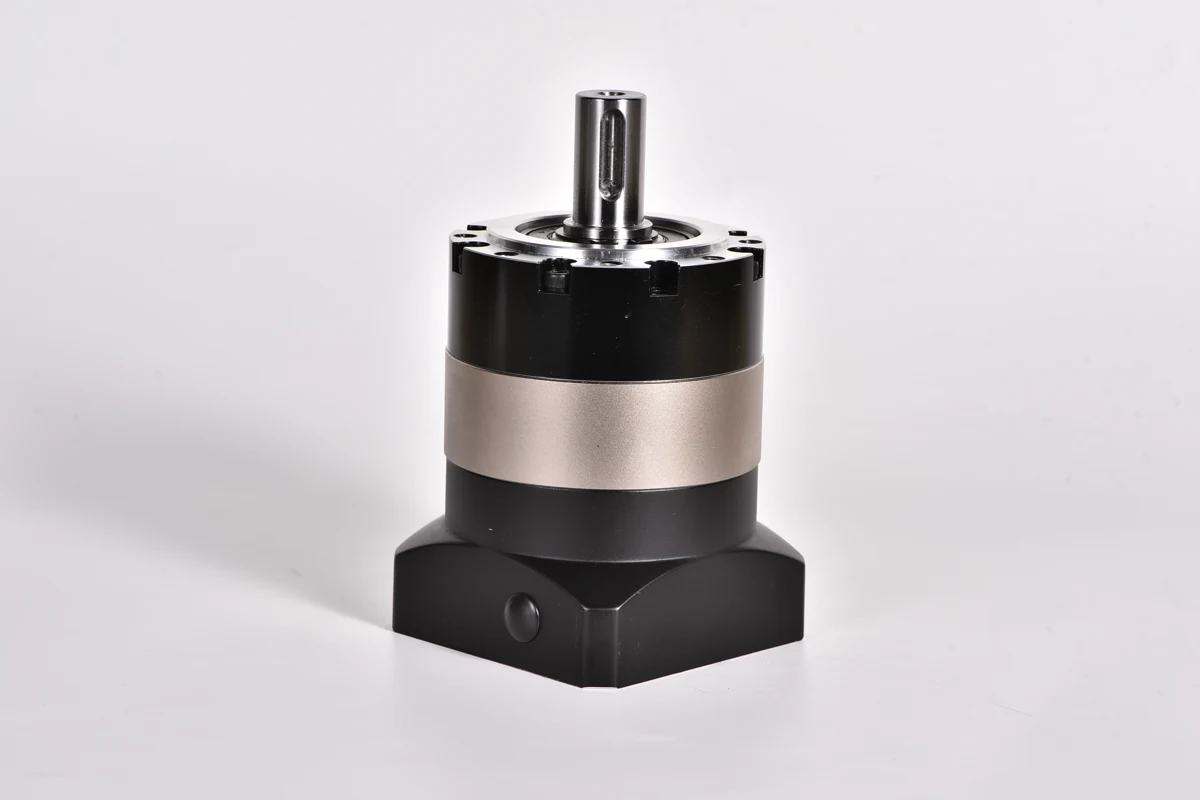
To design a planetary gearbox, first define the input, output and fixed member, then choose the ratio and gear geometry, calculate tooth and bearing loads, and verify stiffness, lubrication, temperature and service life. Choosing tooth counts is only the kinematic starting point. A gearbox that has the correct ratio can still be unsuitable for its working load or positioning duty.
For machine builders, there are two different tasks: designing a gearset from individual components, or specifying a complete planetary gearbox for a machine. This guide explains the connection between them and the information needed for an ANDANTEX selection or custom-interface enquiry.
How the sun, planets, ring and carrier work together
| Member | Role in a common reduction arrangement | Design question |
|---|---|---|
| Sun gear | Central gear driven by the input | Can the teeth and input connection carry the applied load? |
| Planet gears | Mesh with the sun and internal ring while turning on carrier pins | Are tooth loading, pin support and bearing life acceptable? |
| Ring gear | Internal gear fixed to the housing in this arrangement | Can the ring and housing resist their reaction loads? |
| Carrier | Supports the planets and provides the reduced-speed output | Are pin alignment, output support and torsional stiffness sufficient? |
Other arrangements fix or drive different members and produce different speed relationships. Identify the arrangement before using a formula.
Calculate the ratio for a fixed-ring planetary stage
For a simple stage with the ring fixed, sun as input and carrier as output, i = nsun / ncarrier = 1 + Zring / Zsun, where Z is tooth count and n is rotational speed.
As an illustrative geometry, a 20-tooth sun, 40-tooth planets and a 100-tooth ring give a 6:1 reduction. At 3,000 rpm sun speed, carrier speed is 500 rpm. These are teaching values, not the internal tooth counts of an ANDANTEX product.
For an unshifted spur arrangement with matching module, the basic concentric geometry requires Zring = Zsun + 2Zplanet. This is not a complete design check: tooth interference, clearances, planet spacing and assembly phasing must also be verified. See the reduction ratio and L1/L2 guide for selecting a complete gearbox ratio.
Convert the duty into a load specification
Record the output speed, working torque, acceleration and deceleration, reversals, process forces and dwell. Separate normal repeated operation from occasional overload or emergency stopping. Specify the target operating hours and installation environment so that thermal and life assessments have a defined basis.
Also describe what is attached to the output. A belt pulley, pinion, coupling and directly mounted fixture create different shaft and bearing loads. Provide the load location and overhang; an output torque figure alone does not describe the support requirement.
Resolve strength, support and precision together
- Gear teeth: assess bending and contact loading using the actual material, heat treatment, geometry, duty and load distribution.
- Planet pins and bearings: check the supporting components, their fits and their lubrication requirements.
- Carrier and housing: control deflection and alignment so the intended load sharing can be achieved.
- Backlash and stiffness: specify both when the machine reverses or positions under load. A low backlash value alone does not define loaded positioning error.
- Lubrication and temperature: verify the lubricant, seals, mounting orientation and heat generated during the real cycle.
Do not estimate complete gearbox capacity by multiplying one gear’s capacity by the number of planets. Manufacturing variation and structural deflection affect how the load is shared.
When a standard gearbox is the practical starting point
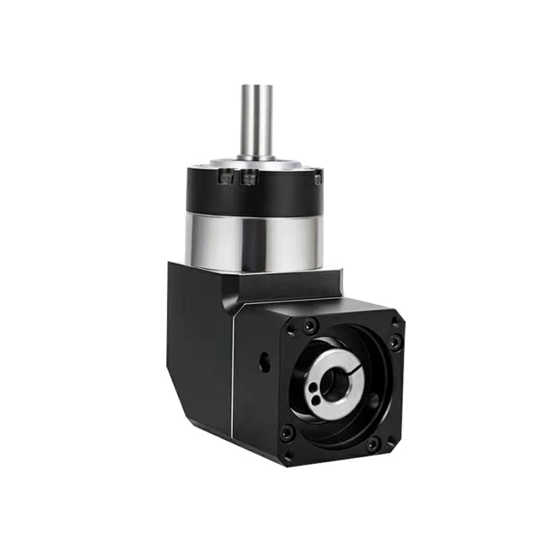
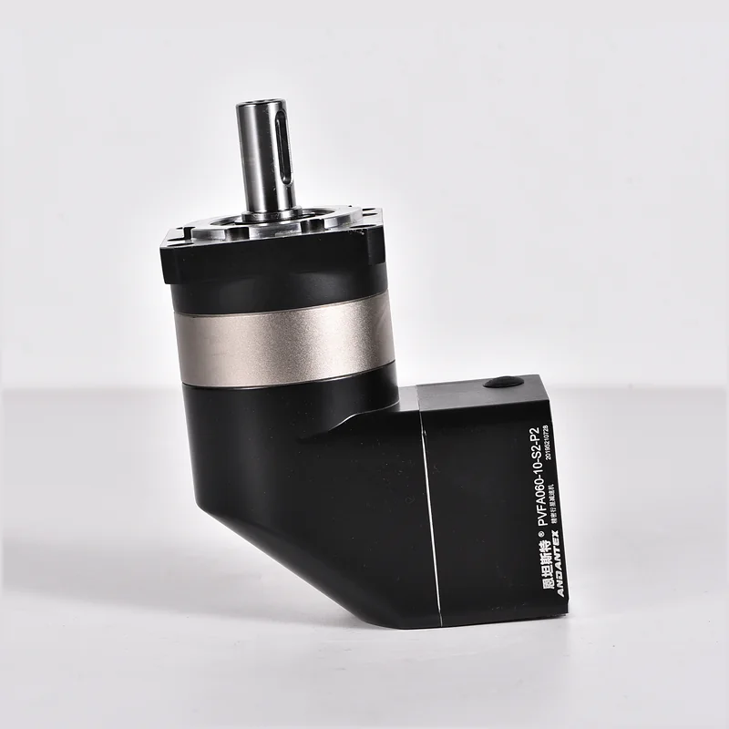
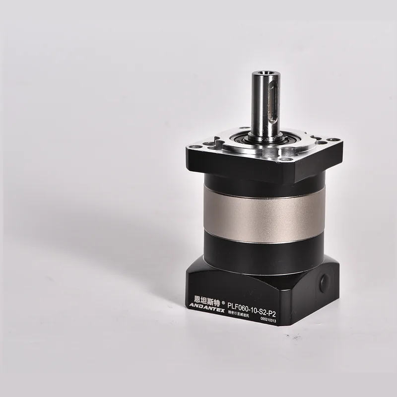
If the machine needs an established reduction unit with a defined motor adapter, start with a complete model and its drawing. Compare PLF standard planetary gearboxes for belt and ball-screw layouts, PAG helical planetary gearboxes for suitable rack-and-pinion or ball-screw duties, and PVFA right-angle planetary gearboxes when the motor arrangement must turn through 90 degrees.
For a custom request, state which feature needs to change: input adapter, output interface, mounting envelope or another defined requirement. Read planetary gearbox selection for servo motors before choosing a candidate.
What to send for an engineering review
Send a machine layout, motor drawing, speed and torque cycle, output load positions, accuracy requirement, target life and quantity. Include the mating-part drawing and the dimensions that cannot change. Use the interface matching tool for an initial comparison, then request an engineering review or discuss OEM and custom interfaces.
Technical reference for planetary geometry and arrangements: KHK Internal Gears technical information. The worked numbers above illustrate the mechanism and do not specify a production gearbox.
Leave a Technical Question