 PRECISION DRIVE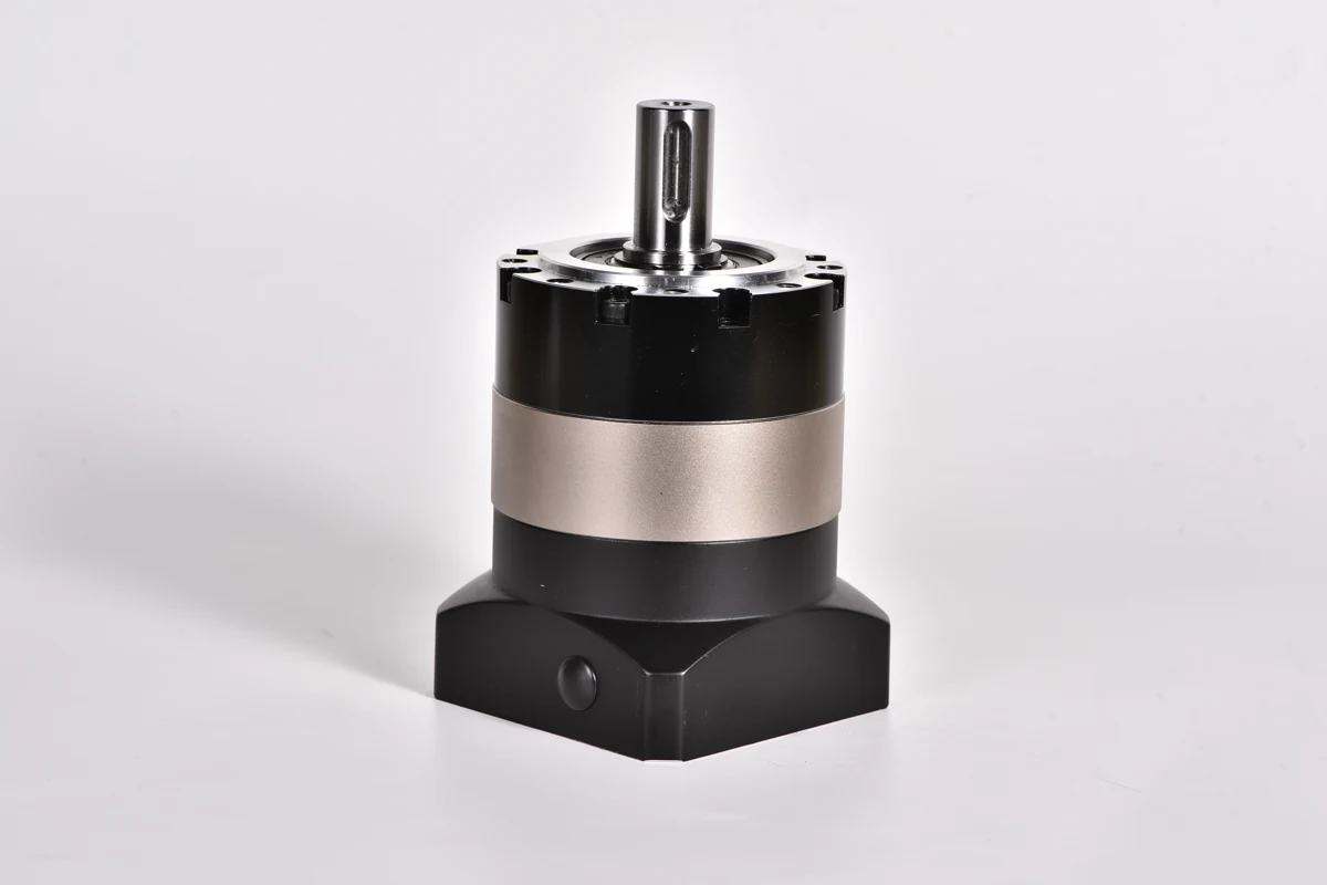
Compare ANDANTEX planetary gearbox series for servo-driven automation. Start with the transmission arrangement and output connection, then check ratio, torque, positioning requirements and the exact motor interface. This overview brings together standard, precision, flange-output and right-angle planetary gearboxes.
Choose a planetary gearbox family
| Series | Configuration | Selection starting point |
|---|---|---|
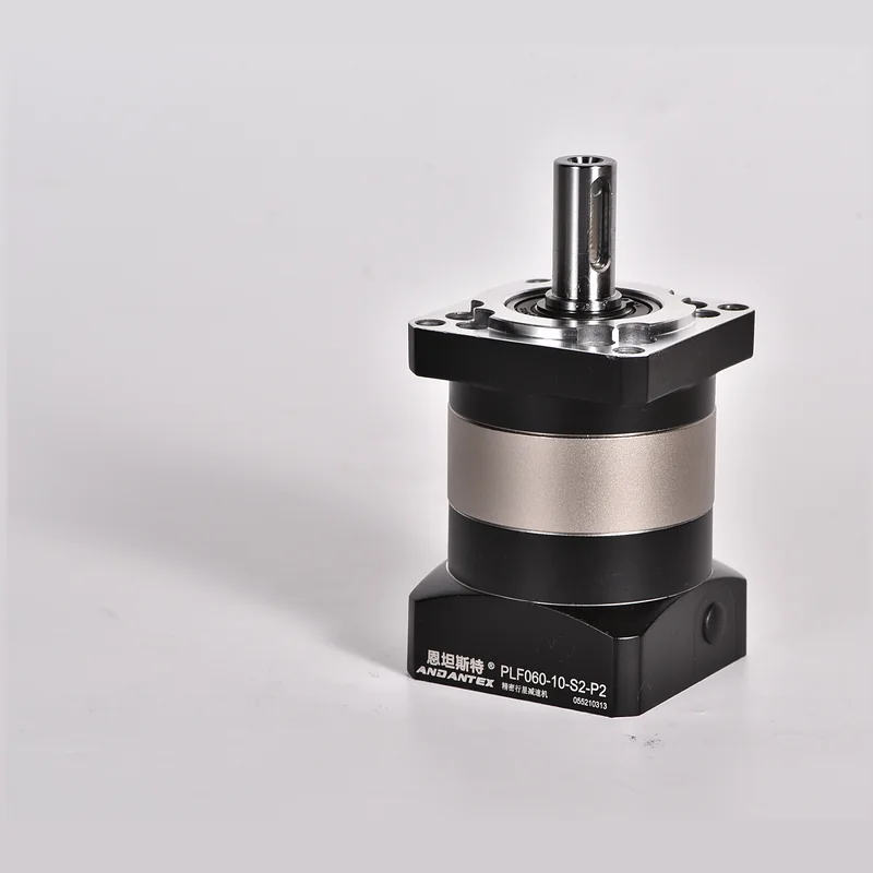
| PLF | Standard planetary gearbox with a square flange | Timing-belt and ball-screw drives |
| PLE | Round-flange planetary gearbox | Machines requiring a round-flange mounting arrangement |
| PAG | Helical planetary gearbox | Rack-and-pinion and ball-screw drives |
| PLM | Precision planetary gearbox | Compare frame sizes and available motor-interface configurations |
| PLX | Flange-output planetary gearbox | Rack-and-pinion drives requiring a flange output |
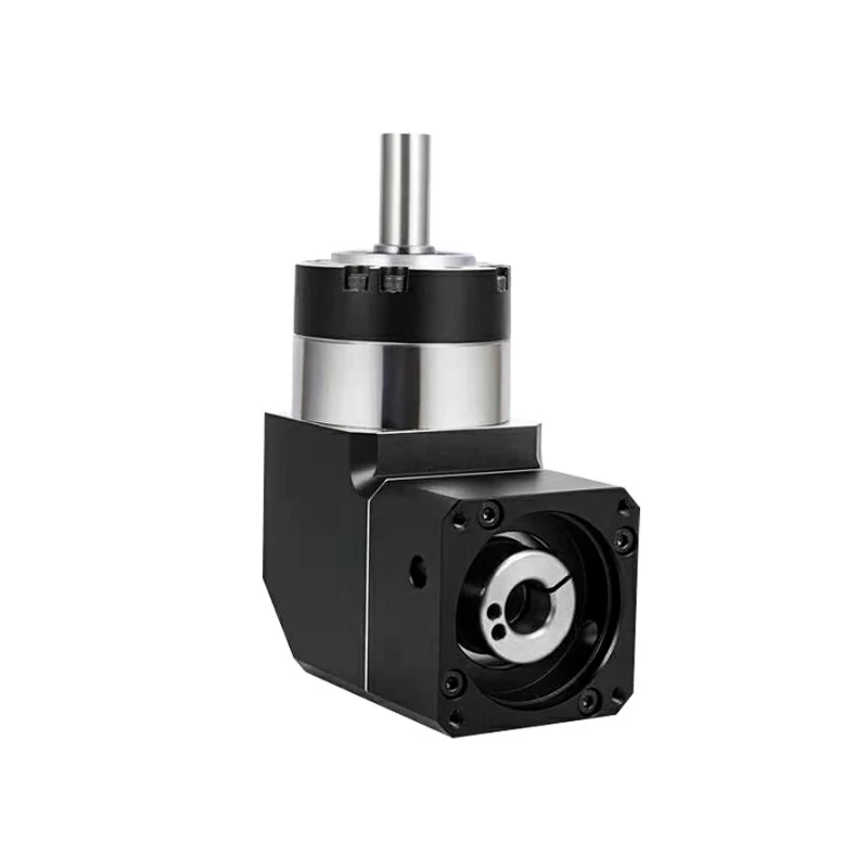
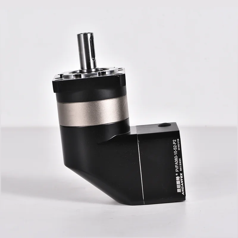
| PVEA / PVFA | Right-angle planetary gearboxes with round / square flanges | Layouts requiring a right-angle motor arrangement |
| PAMG | Right-angle helical planetary gearbox | Compare the required mounting envelope and motor interface |
| PLMX | Right-angle flange-output planetary gearbox | Layouts combining a right-angle input arrangement with a flange output |
Browse the standard planetary gearbox range or the precision planetary gearbox range for additional series and model choices.
Match the gearbox to the transmission
- Timing belts and pulleys: start with PLF, then check the pulley load, overhang and shaft connection.
- Rack and pinion: compare PAG and PLX according to the pinion connection, required torque and positioning duty.
- Ball-screw modules: compare PLF and PAG, accounting for acceleration, inertia and the coupling arrangement.
- Direct coupling: compare suitable series using the load calculation and available installation space; motor power alone does not confirm gearbox suitability.
Confirm ratio, load and motor fit
Choose the reduction ratio from the required output speed and the motor operating range. Check continuous and peak torque, acceleration time, duty cycle, inertia and external radial or axial loading against the selected model specifications. Read the planetary gearbox ratio and L1/L2 guide for the ratio calculation and stage terminology.
Match the motor shaft diameter and length, pilot diameter, mounting-hole spacing and fasteners to the selected gearbox drawing. Two motors with the same power rating may need different input adapters. Use the motor-interface matching tool and confirm the final dimensions on the drawing before ordering.
Drawings and selection support
Open the model page within the chosen series to review specifications and available 2D drawings and 3D STEP files. Engineering resources are configuration-specific: match the model, reduction stage and motor interface before downloading from the engineering download center.
For a quotation, send the motor model or drawing, required ratio, output speed, load, operating cycle and quantity. Request planetary gearbox selection support. Custom labels, packaging and input or output interfaces can be discussed through OEM cooperation.
How to select a planetary gearbox for a servo motor: a working sequence
Start at the driven mechanism and work back to the motor. Define the move, calculate the required output torque, choose a ratio, check the gearbox limits and then confirm the motor interface. A motor power label is a useful catalogue filter, but it is not a complete sizing calculation.
| Check | Information to record | Selection decision |
|---|---|---|
| Motion | Output speed, travel or angle, move time and dwell | Choose a ratio that keeps the motor within its usable speed range |
| Load | Working torque, friction, gravity and acceleration torque | Check continuous duty and each transient against the relevant limits |
| Inertia | Fixture and workpiece inertia about the driven axis | Check reflected inertia and the motor manufacturer’s tuning guidance |
| Output support | Pulley or pinion diameter, overhang, axial and radial force | Check the output bearing and shaft as well as transmission torque |
| Motor fit | Shaft diameter and length, keyway, pilot, bolt pattern | Select the exact input adapter and verify the installation drawing |
Example: a 750 W servo at 3,000 rpm
This is an illustrative calculation, not a rating for a particular ANDANTEX model. At that operating point, motor torque is approximately T = 9550 × 0.75 / 3000 = 2.39 N·m. With a 10:1 reduction, output speed is 300 rpm. If efficiency is assumed to be 95% solely for this example, transmitted output torque is about 2.39 × 10 × 0.95 = 22.7 N·m.
That result does not establish permissible gearbox torque. Compare it with the exact model’s continuous and peak ratings, input-speed limits and duty requirements. If the process needs 40 N·m continuously, this example operating point does not meet the requirement simply because a larger gearbox is fitted. Check the motor’s torque-speed curve and reconsider the ratio or motor.
Check inertia and the complete operating cycle
For an ideal reduction ratio i, load inertia reflected to the motor is Jreflected = Jload / i². Include gearbox and coupling inertia at the appropriate shaft. A higher ratio reduces reflected load inertia but also changes motor speed and acceleration requirements. There is no single acceptable inertia ratio for every servo system.
Record acceleration, constant-speed motion, deceleration and dwell separately. Use the manufacturer’s permitted duty and thermal evaluation method; do not substitute an emergency-stop torque limit for a repeated working peak. A belt-driven axis also needs a bearing-load check using belt tension and pulley overhang.
Turn the calculation into a model enquiry
For a 400 W belt axis, PLF060 is a starting point to investigate; a 750 W application may lead you to compare PLF090 and PAG090, depending on the drive arrangement. These are candidate examples, not automatic motor compatibility approvals.
Use the selection center, then attach the motor drawing and a cycle table to your enquiry. Read rated versus peak torque and motor interface dimensions for the checks behind each decision.
Engineering reference: Oriental Motor: gearing and reflected load inertia. Product limits must come from the selected ANDANTEX configuration.
For the mechanism behind the selection process, read Planetary Gearbox Design: How It Works and What to Specify.
Leave a Technical Question