 PRECISION DRIVE
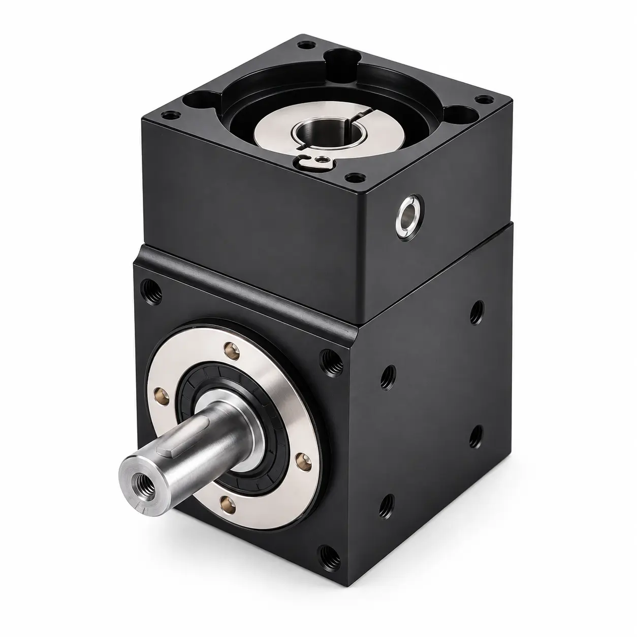
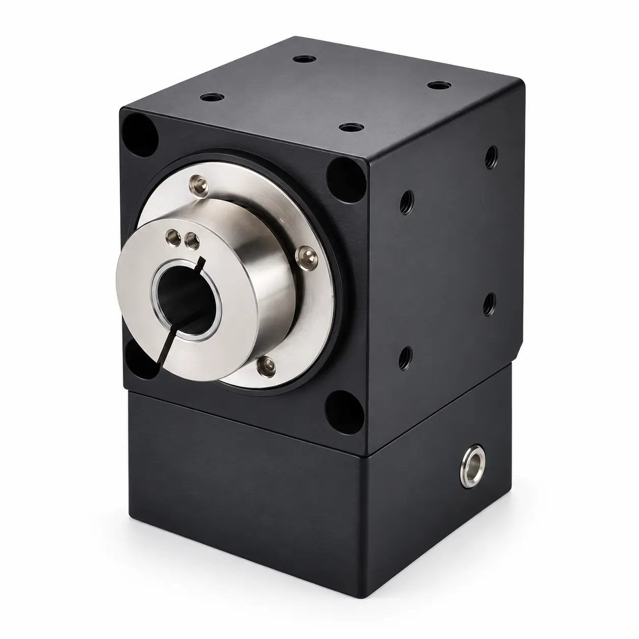
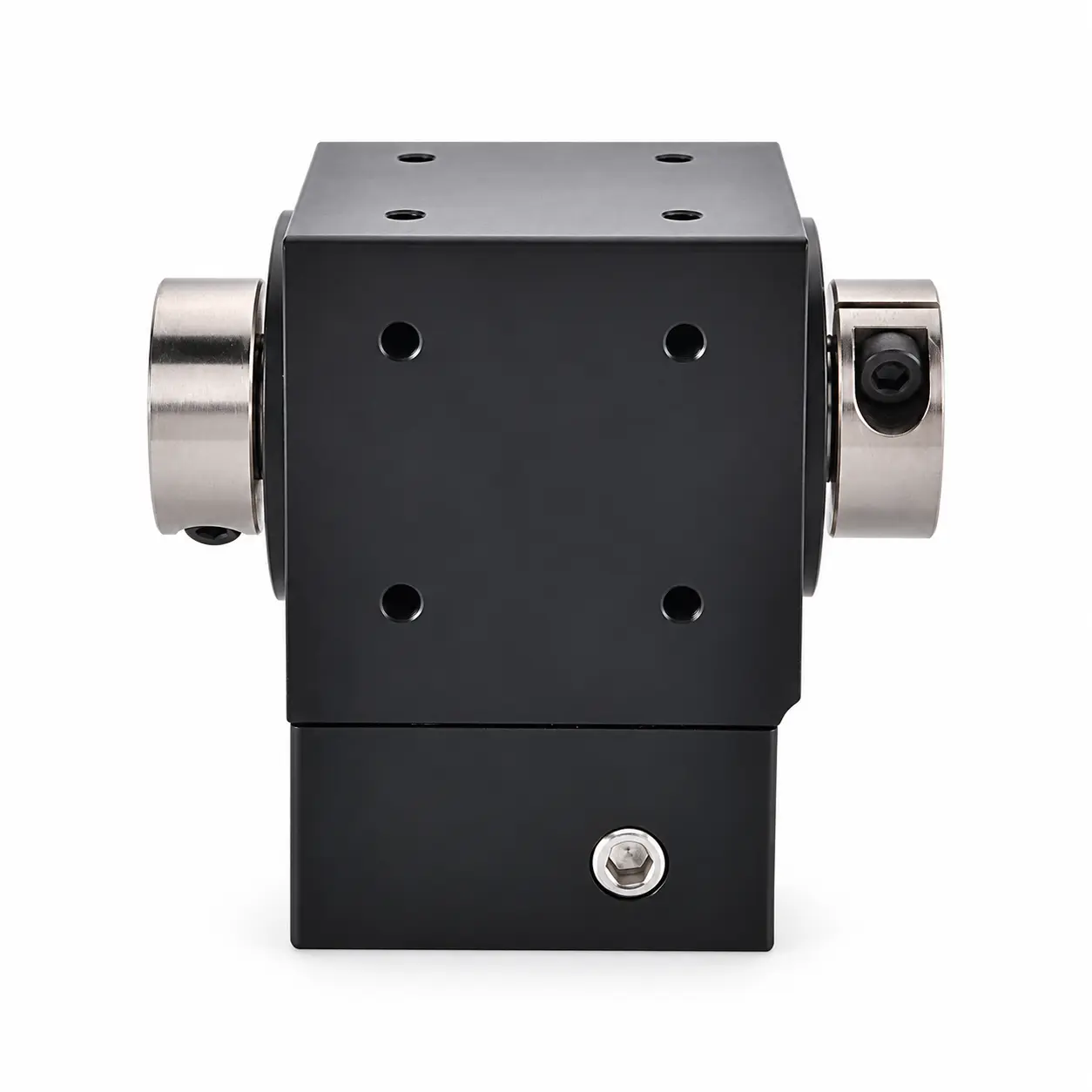
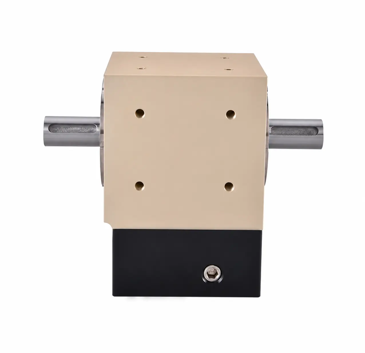
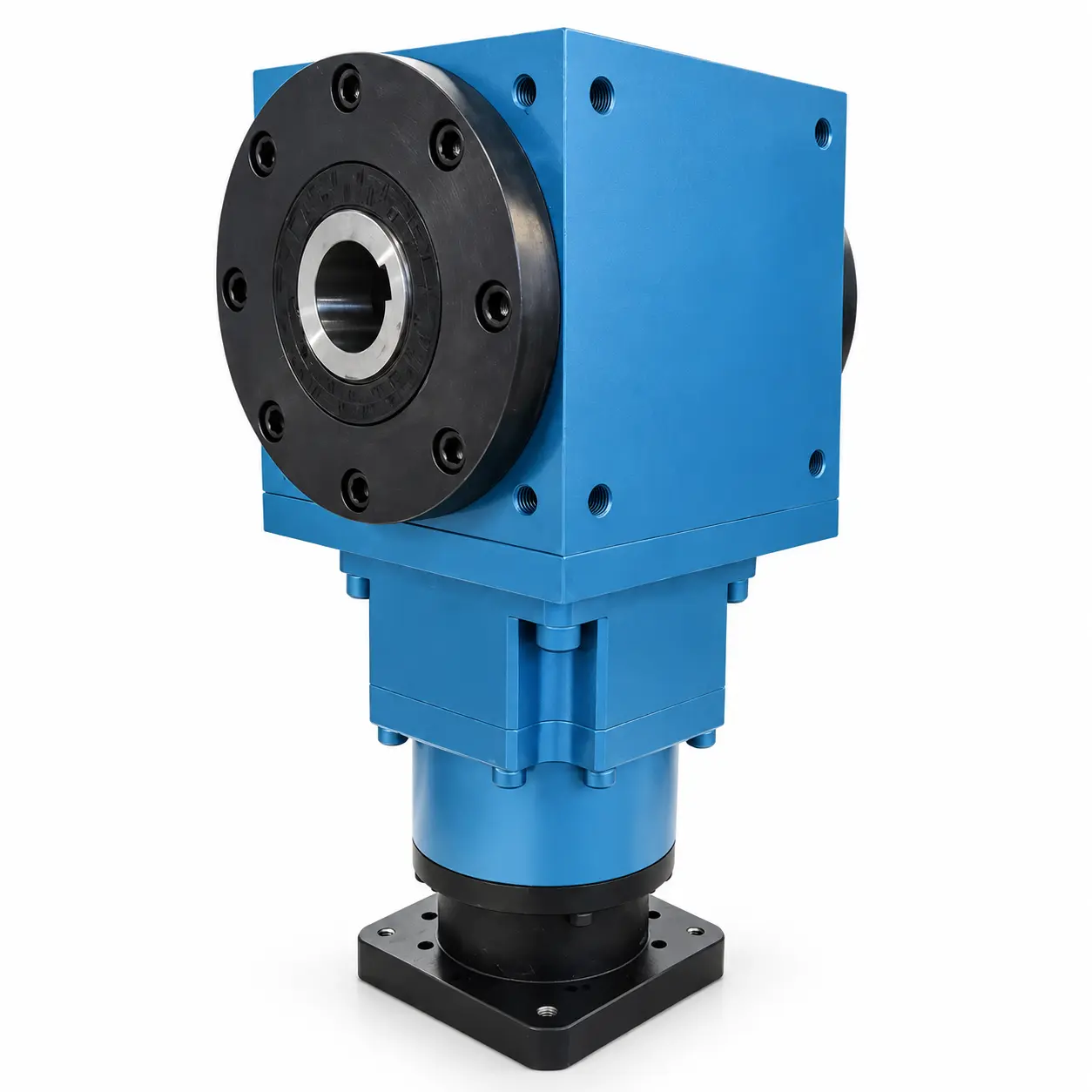
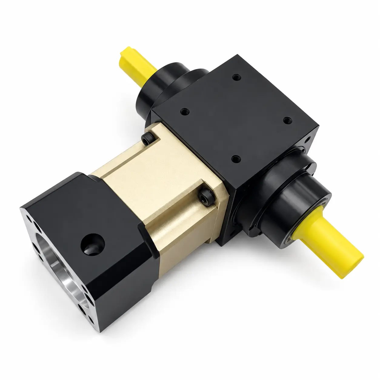
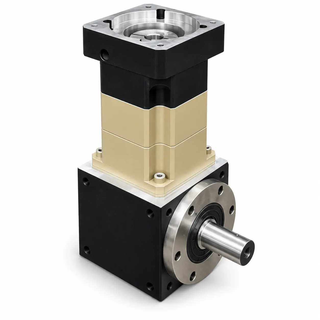
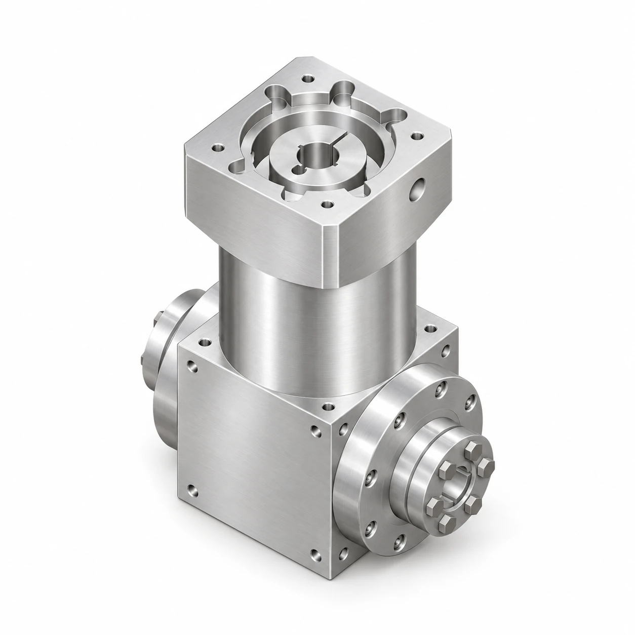
AT140-FH Double Keyed-Bore Output Right-Angle Gearbox
AT140-FH is a double keyed-bore output right-angle gearbox.
The referenced L2 drawing specifies selectable 19, 22 or 24 mm input bores and rated torque of 150 or 270 Nm depending on ratio. Use the actual motor drawing and driven-shaft dimensions to resolve interface fit in an automation layout.
Key Technical Specifications
| Item | Parameters | Description |
|---|---|---|
| Product Series | AT-FH Double Keyed-Bore Output Gearboxes | Right Angle Gearbox |
| Specifications / Frame Size | 140 | Model Specifications |
| Output Structure / Flange Type | Double keyed-bore output | FH output structure confirmed by manufacturer; key and bore dimensions depend on configuration. |
| Gear Ratio | 3, 4, 5, 7, 10 | L2 S-110-145M8 drawing only; other configurations require their own drawing. |
| Rated Output Torque | 150 Nm (3, 10); 270 Nm (4, 5, 7) | L2 S-110-145M8 drawing only; other configurations require their own drawing. Confirm the rating basis for both output connections. |
| Maximum Torque | 230 Nm (3, 10); 420 Nm (4, 5, 7) | L2 S-110-145M8 drawing only; other configurations require their own drawing. Confirm permissible duration and load distribution. |
| Backlash | ≤15 arcmin | L2 S-110-145M8 drawing only; other configurations require their own drawing. |
| Maximum Axial Force | 3300 N | L2 S-110-145M8 drawing only; other configurations require their own drawing. Confirm load application point and rating basis. |
| Maximum Radial Force | 4800 N | L2 S-110-145M8 drawing only; other configurations require their own drawing. Confirm load application point and rating basis. |
| Typical Interface | Input S = 19, 22 or 24 mm; pilot φ110 H7; PCD 145 mm, 4-M8; double φ32 H7 keyed output | L2 S-110-145M8 drawing only; other configurations require their own drawing. |
Unlisted Specifications Are Pending, Confirm for the Specific Configuration.
Find by Interface Dimensions AT140-FH Drawings
Choose the motor interface and reduction stage that match your configuration. Each drawing and STEP file applies to its stated variant.
Enter Motor Shaft Diameter, Pilot Diameter & Mounting Hole Spacing, Find identical or similar input interfaces across recorded models; Resources Requiring Review Are Clearly Marked.
Match Using Dimensions on the Motor Drawing
Filter by motor type, reduction stage and the dimensions on your motor drawing. Matching configurations show their available drawings and STEP files; missing files are marked.
AT140-FH 2D / 3D Engineering Resources
Choose the files for the exact model, motor interface and reduction stage. Dimensional drawings may be images or PDF; 3D models are STEP files.
Check the Model before Downloading, Size & Interface
Check the complete model and configuration against the approved engineering drawing. Custom inputs, outputs and flanges require their own matching files.
Application and Drive-Layout Selection
AT140-FH provides double keyed-bore output in a right-angle transmission layout. For robot peripheral axes, lithium-battery production equipment, semiconductor handling and vision-inspection mechanisms, review the actual motion cycle, installation envelope, cleanliness requirements and positioning target before selecting a configuration.
Match the Gearbox to the Driven Mechanism
- Timing belt: provide pulley diameter, belt tension, acceleration and the distance from the pulley load to its support. Check torque and radial load together. Compare PLF when an inline arrangement is suitable.
- Rack and pinion: provide pinion pitch diameter, travel force, speed and reversal accuracy. Compare PAG or PLX for an inline helical-gear solution; choose a right-angle layout only after checking the required shaft arrangement and backlash.
- Ball screw: provide screw lead, axial thrust, moving mass and support-bearing arrangement. Compare PLF or PAG for inline drive options.
- Direct connection: match shaft or bore diameter, keyway or locking-ring interface, engagement length, alignment and external bearing support to the exact drawing.
For a double-output arrangement, report the load on both sides. Confirm whether each stated torque or force limit applies to one connection or the complete gearbox; ratings from a different series must not be transferred.
OEM, Delivery and Purchasing
Include the complete model, ratio, motor drawing, quantity and destination in your inquiry. Specify OEM branding, packaging or interface customization requirements. Request EXW or FOB terms and, for FOB, name the required port. Production lead time, freight scope and any custom tooling are confirmed in the quotation for the selected configuration.
Request a Configuration and Quote OEM options · Motor interface checklist
AT140-FH Selection FAQ
How do I match a motor to AT140-FH?
Use the motor drawing to check shaft diameter, shaft length and keyway, locating pilot, mounting pitch circle and fastener size. Select the exact stage and interface resource. A keyed input shaft and a coupling input bore require different mating arrangements.
How should I calculate the required load?
Provide load torque, speed, acceleration, duty cycle and any radial or axial forces. Include pulley or pinion geometry, load offsets and both output-side loads where applicable. Confirm the rating and service factor for the complete configuration.
Can this model replace another brand?
Send the existing full model code and dimension drawing. Compare ratio, torque, backlash, output connection, motor interface and installation envelope. Similar frame codes alone do not establish interchangeability.
What should I check before installation?
Follow the selected drawing and installation instructions. Check shaft and bore fits, key dimensions or locking-ring requirements, alignment, engagement and support bearings. Obtain the specified tightening torques for the exact hardware; do not use an assumed value.
Where are 2D, PDF and 3D STEP files?
The engineering resource section lists files by model, stage and interface. PDF is available where supplied. S denotes a selectable input dimension; a STEP for one specific bore does not represent every S variant. Missing files and pairings that require review are identified.
Need a Quote or Engineering Review?
Submit AT140-FH Gear Ratio for, Load & Installation Requirements.