 PRECISION DRIVE
Select a heavy-duty hollow rotary table for a flipping mechanism by checking gravity torque, acceleration torque, bearing loads and the complete fixture layout. Workpiece mass alone cannot determine the model. The center of gravity, axis orientation and time allowed for each move are equally important.
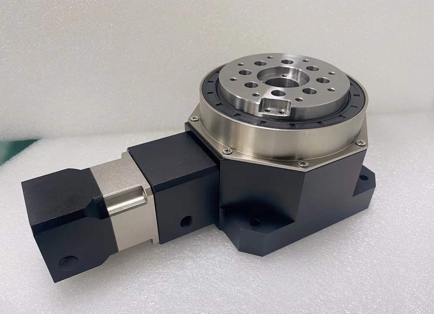
The ANDANTEX HTM series uses a cam roller bearing structure with a hollow flange output. It is offered for custom automation, lithium battery equipment, turnover mechanisms, radar systems and multi-degree-of-freedom platforms. This article focuses on a fixture that turns a workpiece about a horizontal axis; suitability must be checked for the actual configuration.
1. Define what rotates and where its center of gravity sits
Include the workpiece, fixture, gripper, adapter plate and every part that rotates with the table. Record their total mass and center-of-gravity position relative to the rotation axis. Check both loaded and unloaded moves: releasing a workpiece may change the balance of the fixture.
Draw the mechanism at its start, intermediate and end positions. Mark gravity direction, axis direction, clamping forces and process forces. For a lithium battery handling fixture, include the cables and hoses that move with the assembly and the clearance needed around the workpiece.
2. Separate gravity torque from acceleration torque
For a horizontal flipping axis, the maximum gravity torque for a rigid assembly is Tgravity,max = m × g × e, where e is the perpendicular center-of-gravity offset at the worst angular position. The actual gravity torque changes through the rotation. For a vertical rotation axis, weight does not create this same driving torque, although it still loads the support bearings.
Acceleration torque is Tacceleration = J × α, using the total inertia about the driven axis and angular acceleration. Include friction and process torque, with their signs, across the motion profile. The worst values do not necessarily occur at the same instant.
Illustrative load calculation
Suppose the rotating assembly weighs 20 kg and its center of gravity is 0.15 m from a horizontal axis. The maximum gravity torque is approximately 20 × 9.81 × 0.15 = 29.4 N·m. If the assembly inertia is 0.8 kg·m² and acceleration is 4 rad/s², the acceleration component is 3.2 N·m.
If those components oppose the drive at the same instant, their combined demand is about 32.6 N·m before friction, process forces and the chosen design margin. This calculation is not an HTM capacity claim or a recommendation for HTM105, HTM130 or HTM180. It supplies input for checking a model’s verified ratings.
3. Check bearing loads and the supporting machine frame
Driving torque about the rotation axis differs from the overturning moment that tends to tilt the output flange. A fixture extending away from the mounting face may impose both. Calculate axial force, radial force and overturning moment at the specified reference position and compare simultaneous loading with the selected unit’s allowable conditions.
Review the adapter plate, fasteners, mounting face and machine frame along the same load path. A heavy-duty rotary table cannot compensate for an inadequately supported fixture. The spindle and load-support guide explains these distinctions in more detail.
4. Specify the complete move and holding requirement
| Operating detail | What to provide |
|---|---|
| Flip | Angle, direction, time per move and acceleration/deceleration profile |
| Dwell | Holding time, fixture orientation and any force applied during the process |
| Production cycle | Moves per minute, hours per day and loaded/unloaded sequence |
| Positioning | Required angular tolerance, repeatability and settling time |
| Abnormal stop | Stopping sequence, possible gravity motion and required load restraint |
Do not assume the table is self-locking. Confirm how the mechanism holds an unbalanced load when drive power is removed, and include the required brake, restraint and machine guarding in the equipment design.
5. Match the hollow passage, motor and drawing
Check the usable center opening after fitting the adapter and fixture. Hoses and cables need adequate clearance and bend radius throughout the move. Continuous rotation may require a suitable rotary union or slip ring; a hollow bore alone does not prevent cable twist.
Compare the published pages for HTM105, HTM130 and HTM180. Verify motor shaft diameter and length, pilot diameter, mounting holes and the output connection on the exact configuration drawing.
Current HTM105 engineering resources include two-dimensional drawings. Three-dimensional files are still pending for listed configurations; request the required model instead of substituting a different size or interface. Unlisted load, torque and ratio specifications require confirmation before ordering.
Send a fixture drawing for HTM selection
Provide the rotating mass, center-of-gravity coordinates, inertia, motion cycle, motor model, mounting orientation and required positioning tolerance. Add the fixture drawing and any process-force information. Request HTM flipping-mechanism selection support with these details so the correct size and interface can be reviewed.
Leave a Technical Question