 PRECISION DRIVE
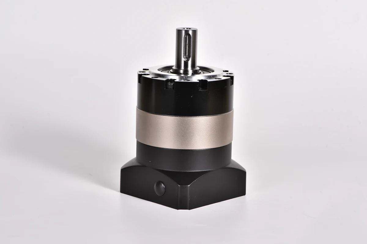
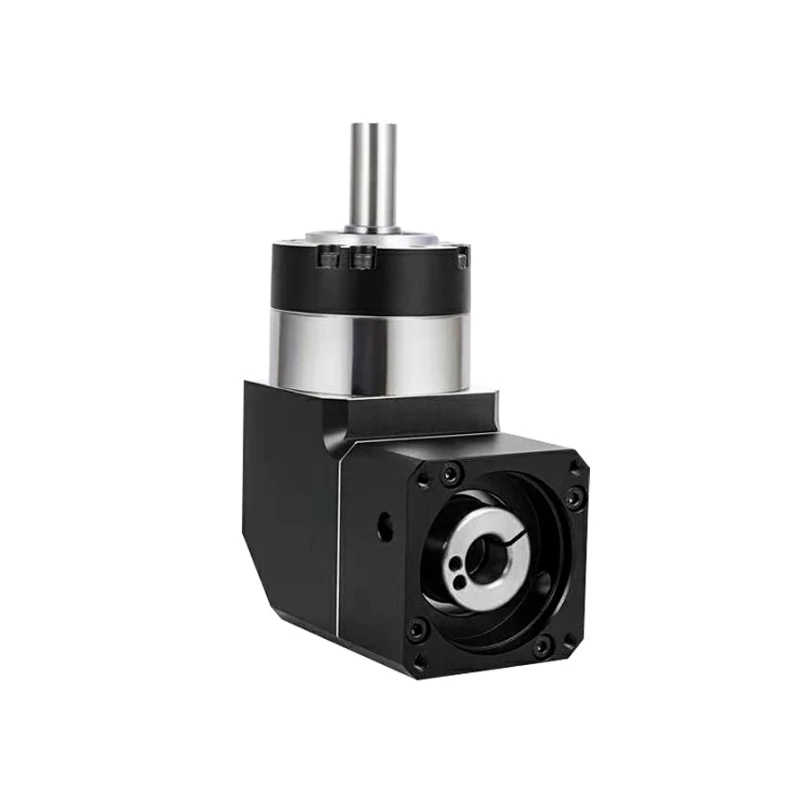
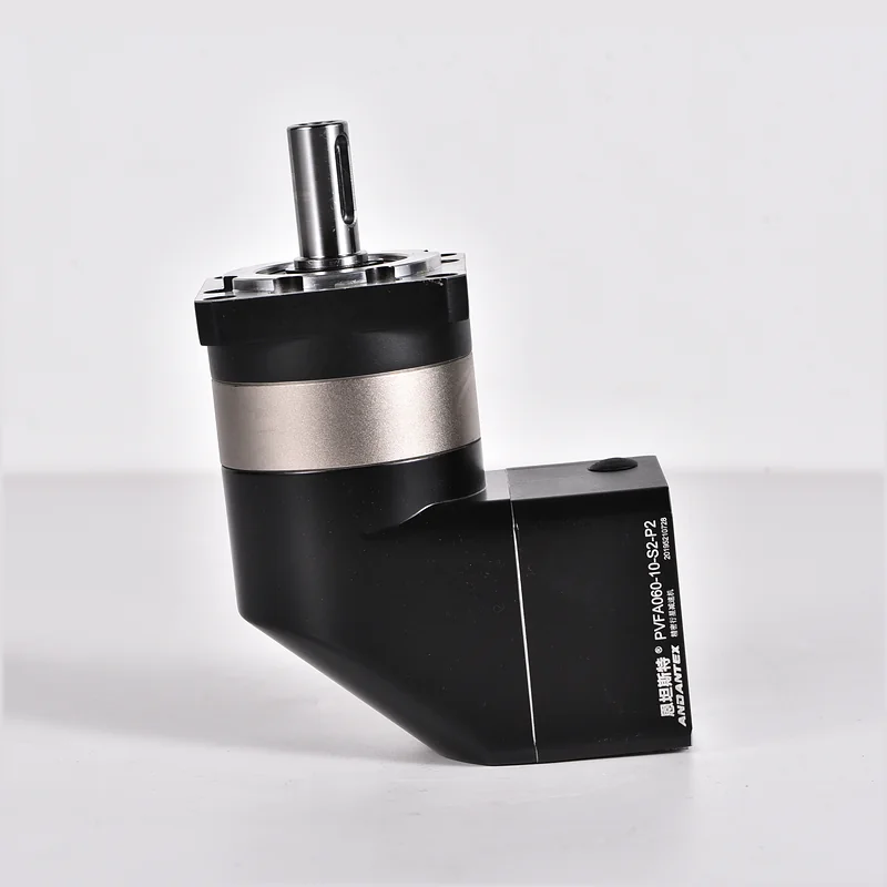
In everyday Chinese gearbox discussions, the informal term translated as “bore input” often means an input bore equipped with a coupling to accept the servo motor shaft. For an engineering inquiry, the clearer description is coupling-bore input. A bore alone does not identify the connection: splined-bore inputs and keyed-bore inputs are other arrangements, while shaft input uses a projecting input shaft.
Start by identifying the input connection, then match the motor drawing to the gearbox interface. Choose the output arrangement separately according to the equipment being driven.
What is a coupling-bore input?
A coupling-bore input receives the motor shaft through a coupling at the gearbox input. In servo applications, the motor shaft and this coupling interface must match. Describing the arrangement only as “hollow input” leaves out the coupling and can create uncertainty when comparing drawings or requesting a quotation.
In this article, coupling-bore input means an input bore with a coupling for the motor shaft. The term does not specify a universal coupling design, clamping method or bore dimension. Those details belong to the selected model and its interface drawing.
Four gearbox input arrangements compared
| Input arrangement | What the description identifies | What to confirm |
|---|---|---|
| Coupling-bore input | An input bore with a coupling that receives the motor shaft. | Motor shaft diameter and usable length, coupling interface and motor mounting dimensions. |
| Splined-bore input | An internally splined input bore that mates with a matching splined shaft. | The specified spline geometry, fit and engagement length shown on the mating drawings. |
| Keyed-bore input | An input bore with a keyway for a matching shaft-and-key connection. | Bore and shaft dimensions, key and keyway dimensions, engagement and retention details. |
| Shaft input | A projecting shaft at the gearbox input rather than a receiving input bore. | The shaft drawing and the connection between the driving equipment and the gearbox input shaft. |
These names describe connection features. They do not, by themselves, establish motor compatibility, torque capacity or positioning performance. A coupling may also have a specified keyed or splined connection, so use the complete drawing to describe an actual assembly rather than treating the four labels as mutually exclusive mechanical standards.
Which dimensions must match the servo motor?
A motor power rating or flange size is a starting point for selection, not a complete interface specification. Before confirming a gearbox, provide the motor model and dimensioned drawing, including:
- Shaft diameter and usable shaft length: compare these with the selected input interface and available engagement depth.
- Shaft connection details: identify a plain shaft, key and keyway, or spline, with the applicable dimensions.
- Motor pilot diameter: check the locating feature against the gearbox input flange.
- Mounting-hole pattern: check hole spacing or pitch-circle diameter, hole quantity and thread or clearance-hole dimensions.
- Assembly details: confirm the relevant shoulders, clearances, fastening method and mounting instructions for that configuration.
For a broader selection workflow, see planetary gearbox selection for servo motors. Motor speed, required output torque, duty cycle and installation space still need to be reviewed alongside the mounting interface.
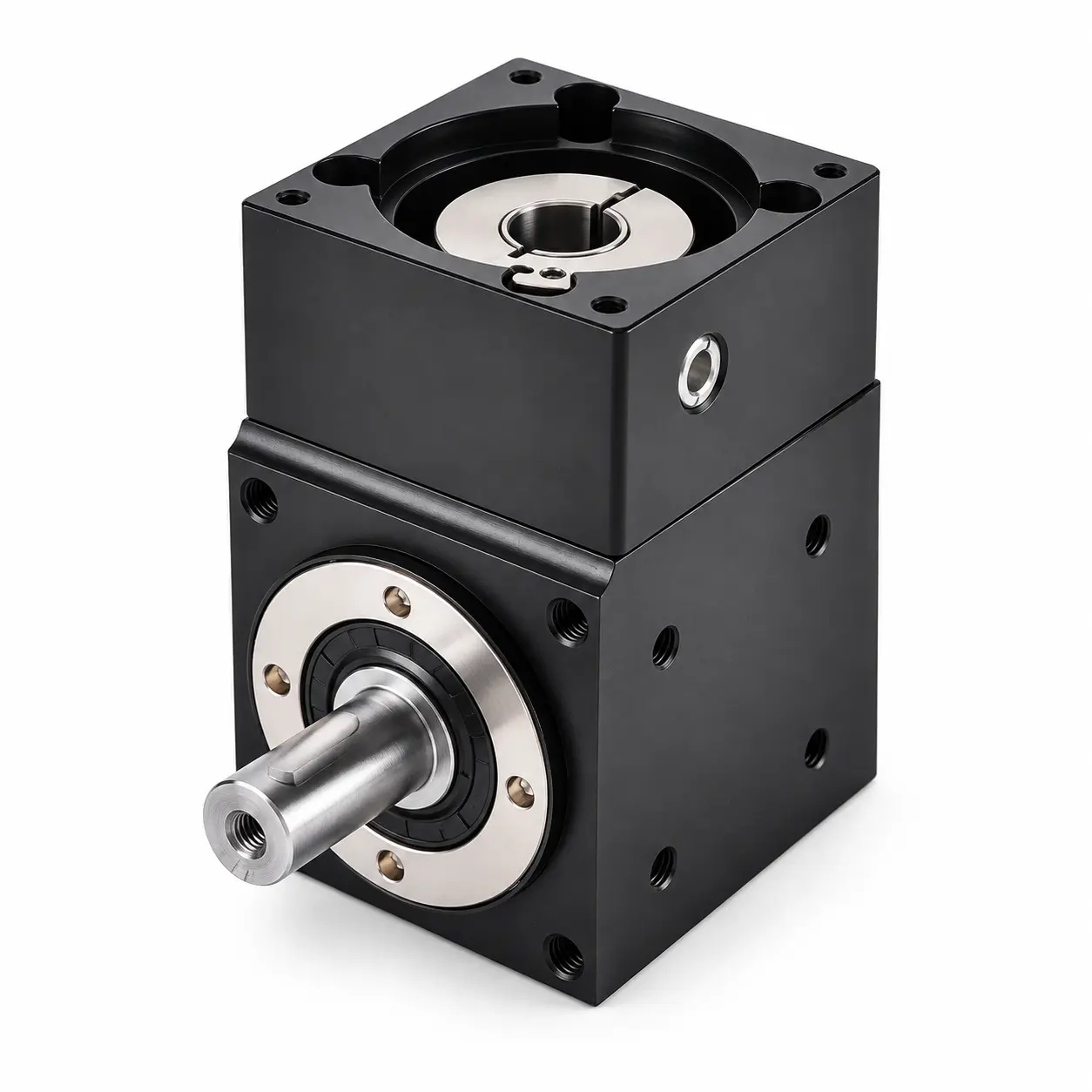
The same input type can have different output arrangements
ANDANTEX PVFD, PVFH, PVFG and PVFGB all use coupling-bore input. Their output arrangements differ:
| Series | Input | Output |
|---|---|---|
| PVFD | Coupling-bore input | Single-shaft output |
| PVFH | Coupling-bore input | Double-shaft output |
| PVFG | Coupling-bore input | Double-bore output |
| PVFGB | Coupling-bore input | Single-bore output |
PVFH and PVFG can connect loads on both output sides simultaneously. For these arrangements, the specified rated output torque is the combined limit for both sides, not the full rated torque available independently at each side. Provide the load requirements for each side when requesting selection support; do not assume an equal load split.
How should you describe the input when requesting a quotation?
Use the connection type, required output arrangement and actual motor drawing together. For example:
“We need a right-angle gearbox with coupling-bore input for the attached servo motor and single-shaft output. Please check the shaft diameter and length, motor pilot, mounting-hole pattern and required output load.”
For a splined or keyed interface, attach the corresponding shaft and bore details. For shaft input, show how the driving equipment will connect to the gearbox shaft. A photo can help identify the arrangement, but a dimensioned drawing is needed to check the fit.
Send your motor drawing and application requirements to ANDANTEX to confirm the input connection and the appropriate output arrangement before ordering.
Leave a Technical Question