 PRECISION DRIVE
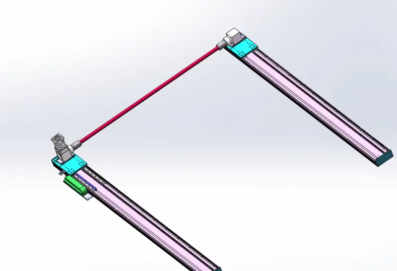
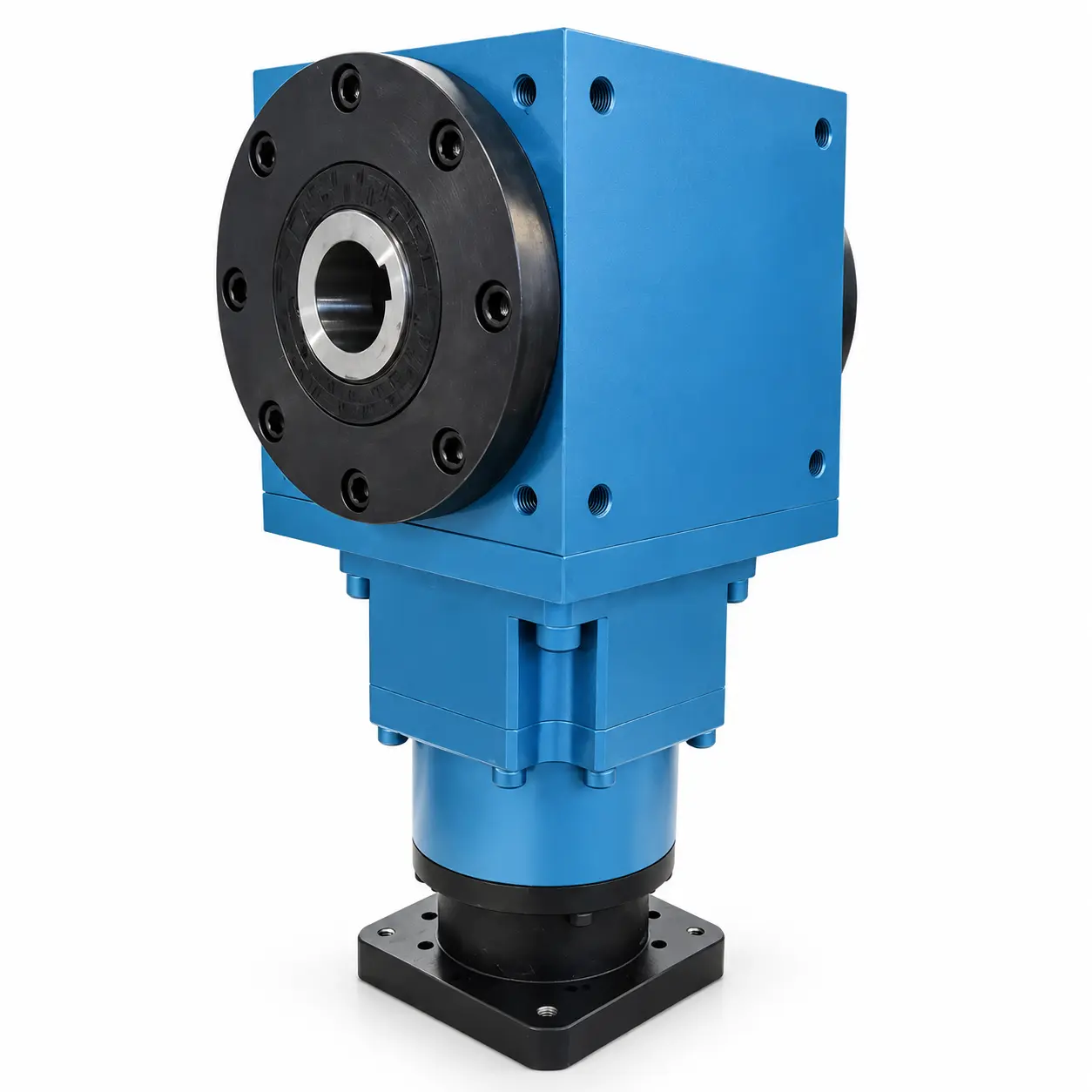
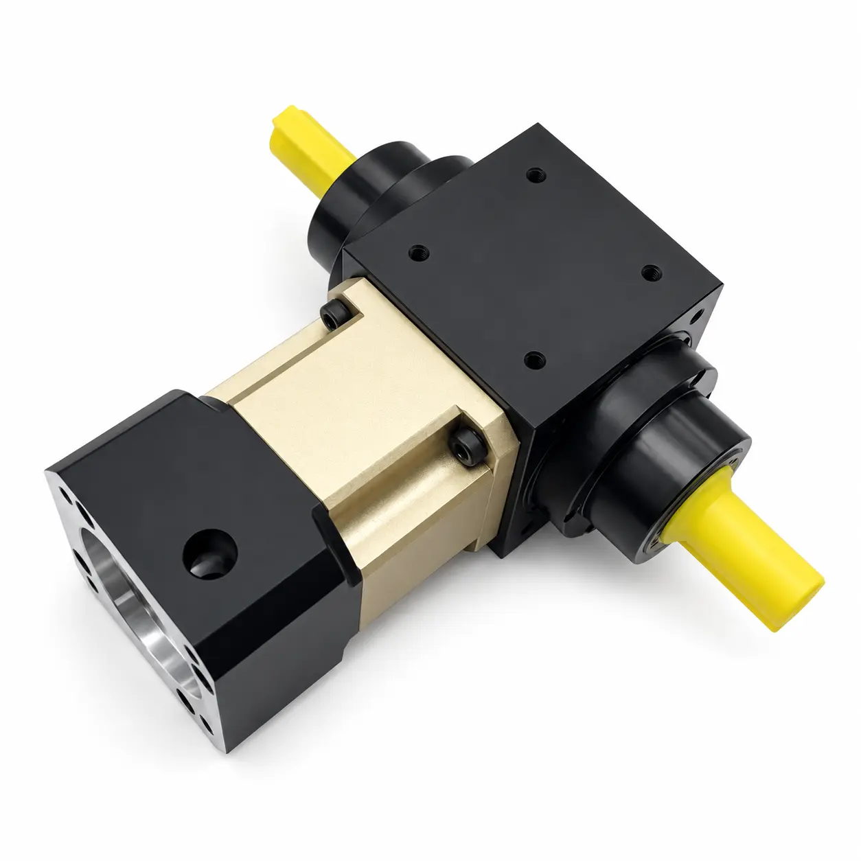
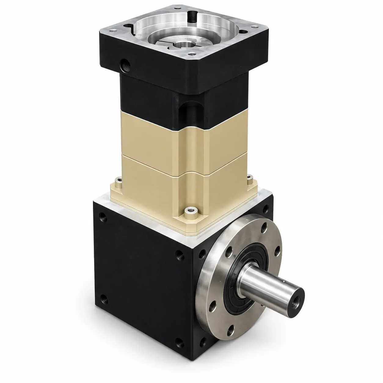
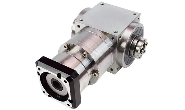
Right-Angle Gearboxes for 90-Degree Drives
Compare ANDANTEX right-angle gearbox series by input connection, shaft or bore output, and installation space. For PVFD, PVFH, PVFG and PVFGB, use the connection guide below, then open a series to check models and drawings.
Product Series
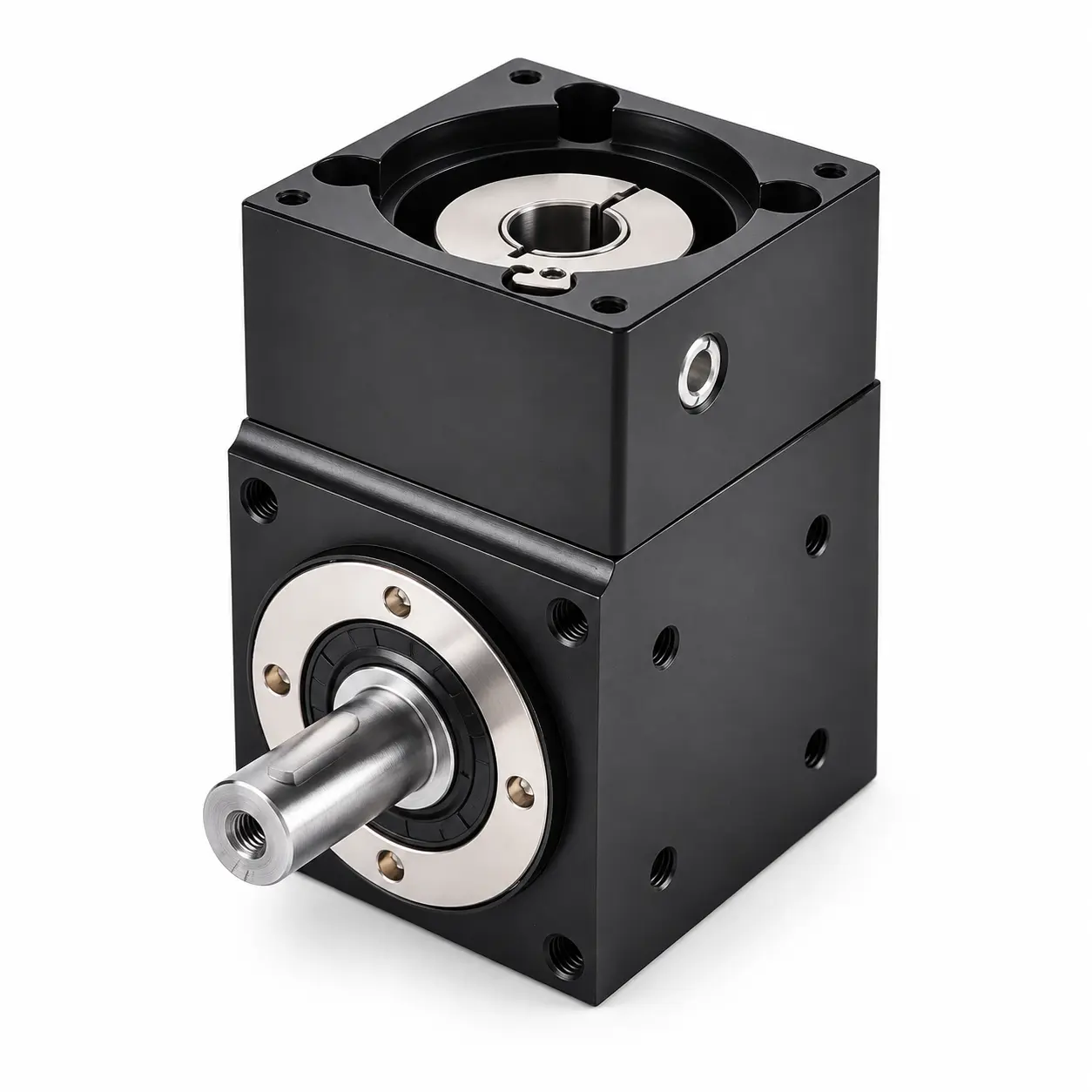
← BackProductsPVFD Single-Shaft Output Series
3 Published Models
View ModelPVFGB Single-Bore Output Right-Angle Gearbox
3 Published Models
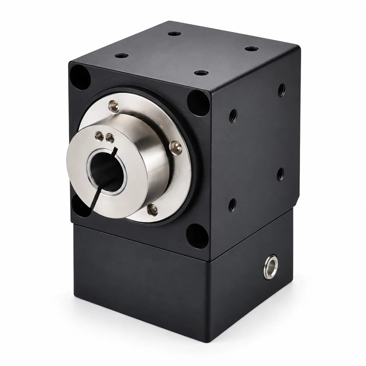
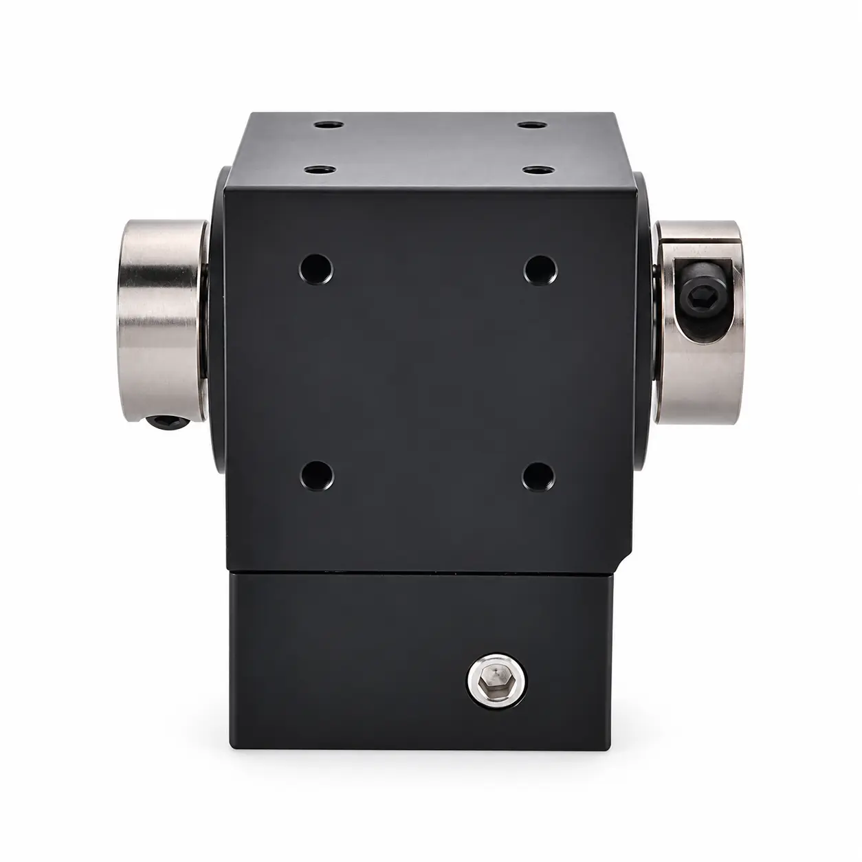
View ModelPVFG Double-Bore Output Right-Angle Gearbox
3 Published Models
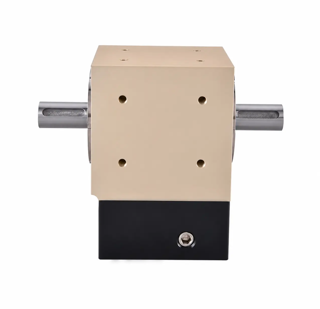
View ModelPVFH Double-Shaft Output Right-Angle Gearbox
3 Published Models
View ModelPVFT-PVD Synchronous Gantry Gearbox
0 Published Models
View ModelAT-FH Double Keyed-Bore Output Gearboxes
9 Published Models
View ModelAT-FL Hollow Input with Dual Shaft Outputs
6 Published Models
View ModelAT-FL1 Hollow Input & Single Shaft Output
6 Published Models
View ModelAT-FC / AT-FC1 Gearboxes with Locking Rings
6 Published Models
View ModelPVFD, PVFH, PVFG and PVFGB: Input and Output Connections
These four ANDANTEX series use coupling-bore input to match a servo motor shaft. Choose the output arrangement required by the machine, then verify the exact model drawing.
| Series | Input | Output |
|---|---|---|
| PVFD | Coupling-bore input | Single-shaft output |
| PVFH | Coupling-bore input | Double-shaft output |
| PVFG | Coupling-bore input | Double-bore output |
| PVFGB | Coupling-bore input | Single-bore output |
Coupling-bore input refers to an input bore equipped with a coupling for the motor shaft. See the guide to coupling-bore, splined-bore, keyed-bore and shaft inputs for connection terminology.
How Is Torque Rated for Both Output Sides?
PVFH and PVFG can connect loads on both output sides simultaneously. The rated output torque is the combined limit for both sides, not a separate full rating available at each side. Check the two loads together when selecting a model; do not assume an equal load split.
Confirm the required output arrangement and load conditions against the model data and drawings before ordering.
What to Check Before Choosing a Model
- Motor connection: provide the complete motor model and check shaft diameter, usable shaft length, locating pilot and mounting-hole pattern.
- Output arrangement: specify single-shaft, double-shaft, single-bore or double-bore output and provide the mating dimensions.
- Operating duty: provide the required ratio, output speed, torque, load inertia and acceleration/deceleration cycle.
- Installation: check mounting space, orientation and access against the selected model drawing.
Use the servo motor interface dimensions checklist to prepare your drawing information. For a model review, send your motor drawing and application requirements.