 PRECISION DRIVE
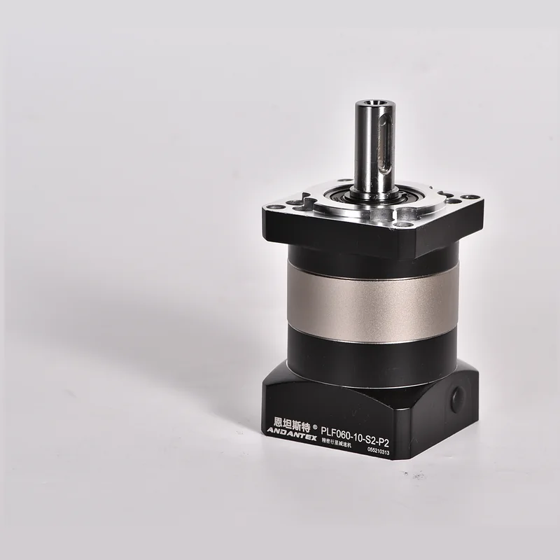
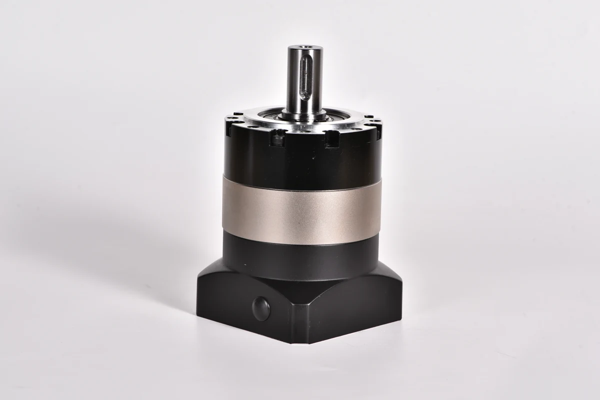
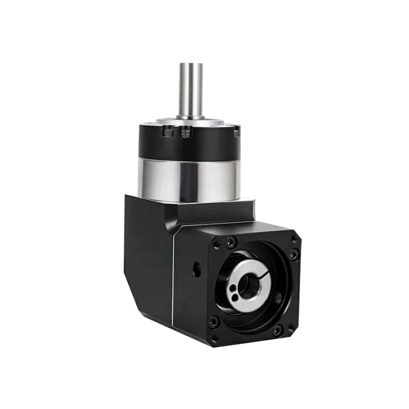
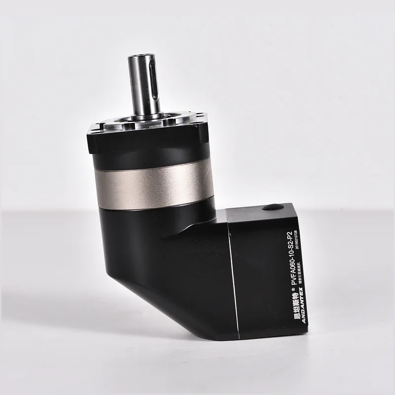
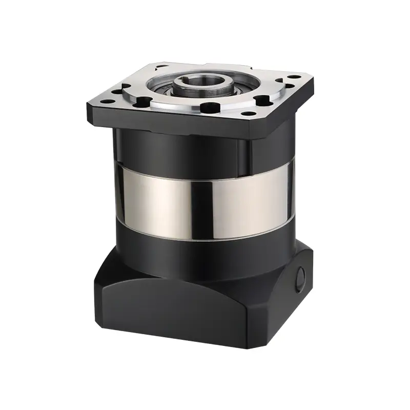
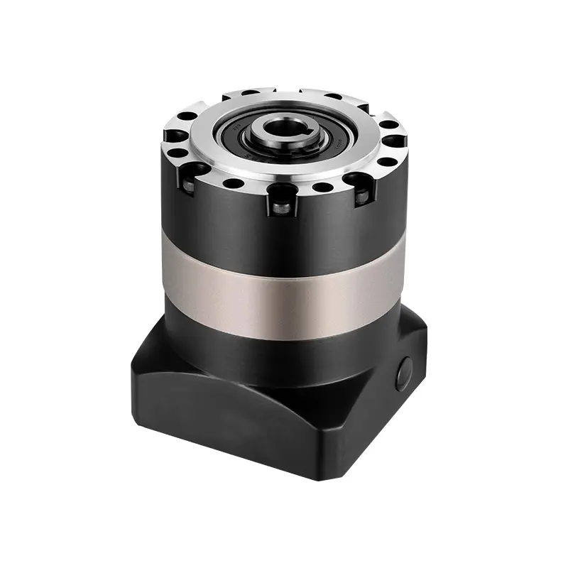
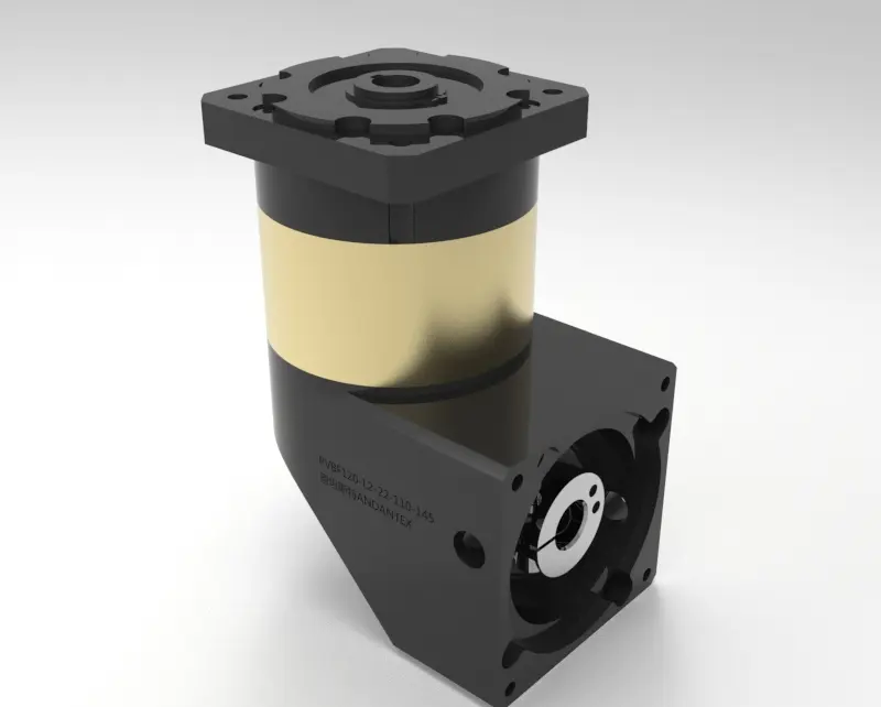
A right-angle bevel gearbox changes the direction of rotary motion through a bevel gear arrangement. In a 90-degree design, the input and output axes meet at a right angle. For machine selection, first confirm the actual gear arrangement and ratio, then specify the shaft or bore connections, rotation direction and load on each output.
Right-angle describes a layout, not one gear type
A right-angle gearbox may use bevel, hypoid or worm gearing, or combine a direction-changing stage with planetary reduction. Bevel gears have intersecting axes; hypoid gearing uses offset axes. A right-angle planetary gearbox and a simple bevel unit should therefore not be treated as equivalent just because both turn the drive through 90 degrees.
Straight and spiral bevel refer to different tooth geometries. If a specification calls for a spiral bevel gearbox, request confirmation of the internal design rather than inferring it from a housing photograph. Confirm performance from the complete gearbox specification.
| Arrangement | Selection question |
|---|---|
| Bevel direction-changing stage | Does the available ratio provide the required output speed? |
| Right-angle planetary arrangement | Does the combined reduction meet the servo axis speed, torque and positioning requirements? |
| Worm arrangement | Are efficiency, thermal duty and backdriving behavior appropriate for the application? |
| Hypoid arrangement | Does the offset geometry suit the envelope and approved load cycle? |
Specify each connection independently
Separate the motor-side input from the machine-side output. A coupling-bore input does not imply a hollow output, and a bore output does not by itself identify a keyway, spline or clamping method. Use the selected drawing to confirm engagement length, fit, location and retention.
- Single shaft output: provide the driven hub or coupling drawing and the force applied to the shaft.
- Single bore output: provide the mating shaft drawing and the intended assembly and retention method.
- Double shaft or double bore output: identify the load, support and required motion on both sides.
- Hollow-shaft requirement: state whether a through passage is actually required and which components must pass through it.
Compare the published ANDANTEX connection layouts in the right-angle gearbox category, including PVFD single-shaft output, PVFGB single-bore output and PVFG double-bore output. These links identify output arrangements; confirm the internal gearing and ratio for the exact model before ordering.
Check rotation direction and shared output torque
Mark the input and output arrows on the assembly drawing and state the viewing direction for each arrow. Descriptions such as clockwise can become ambiguous when the observer moves to the opposite shaft end. For a multi-output machine, include the required relationship between both driven mechanisms.
For the ANDANTEX PVFG double-bore series, the published output torque rating is the combined limit for both sides, not an independent full rating for each side. Supply both loads and their timing; do not assume equal sharing or double the available torque.
Example: driving two mechanisms from one motor
For an illustrative machine with two driven shafts, provide each shaft's working torque, peak torque and cycle timing, together with external support locations. A common drive may simplify the layout, but the connection still needs a torsional and alignment review. Synchronized rotation does not remove deflection or installation errors in the downstream system.
Frequently asked questions
Is every 90-degree gearbox a 1:1 unit?
No. Shaft angle and speed ratio are separate specifications. State the required ratio explicitly and confirm availability.
Can a right-angle gearbox hold a vertical load without a brake?
Do not infer load-holding behavior from the layout or gear name. Review the application with an appropriate braking and load-retention design.
For a servo reduction requirement, also read right-angle planetary gearbox selection. Request a layout and drawing review with all shaft connections, load data and rotation arrows.
Technical reference: KHK bevel and hypoid gear guidance explains gear families and shaft arrangements. Model-specific ratings must come from the selected gearbox specification.
Leave a Technical Question