 PRECISION DRIVE
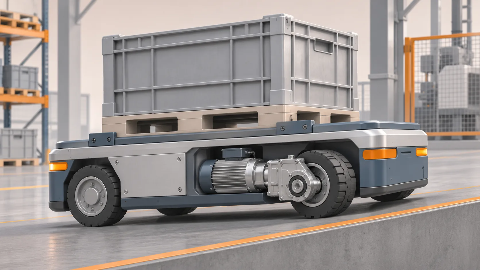
To size an AGV wheel-drive gearbox, start with the total moving mass, required vehicle speed, wheel diameter, slope and acceleration. Use those inputs to estimate wheel speed and traction torque, then check each gearbox, motor, wheel and mounting interface against its actual ratings.
The worked example below is illustrative, not a measured customer test or a rating for a particular ANDANTEX model. It uses two driven wheels sharing the load equally. Real vehicles need additional checks for acceleration, traction, uneven weight distribution, braking and duty cycle.
Step 1: define the duty
Assume an AGV carries a load on a hard floor with the following preliminary inputs:
| Input | Example assumption |
|---|---|
| Total vehicle plus cargo mass | 600 kg |
| Number of driven wheels | 2, assumed to share force equally |
| Effective wheel diameter | 160 mm |
| Target vehicle speed | 5 km/h |
| Uphill grade | 5% |
| Rolling-resistance coefficient | 0.02, assumed for this example |
| Motor speed used for ratio comparison | 3,000 rpm |
Use the total moving mass, not cargo mass alone. Actual rolling resistance must reflect the wheel material, floor, bearings and loading. A 5% grade means a rise of 5 units per 100 horizontal units; it is not an angle of five degrees.
Step 2: calculate wheel speed
Convert the target speed to metres per second:
5 km/h ÷ 3.6 = 1.389 m/s
The wheel circumference is π × 0.160 ≈ 0.503 m. With no slip, wheel speed is:
wheel rpm = vehicle speed (m/s) × 60 ÷ wheel circumference (m)
For the example, 1.389 × 60 ÷ 0.503 ≈ 166 rpm.
The ratio for a motor running at 3,000 rpm is therefore approximately 3,000 ÷ 166 = 18.1:1. That is a starting point, not a statement that an 18.1:1 gearbox is available or that the motor should always operate at 3,000 rpm.
| Example ratio | Output at 3,000 rpm input | Approximate vehicle speed with a 160 mm wheel |
|---|---|---|
| 20:1 | 150 rpm | 4.52 km/h |
| 24:1 | 125 rpm | 3.77 km/h |
At 24:1, reaching 5 km/h with the same wheel would require approximately 3,980 rpm at the motor. Confirm that this speed is available at the required torque and permitted by the motor and gearbox; do not assume a headline maximum speed is continuously usable.
Step 3: estimate the steady climbing force
Let m be total mass in kg, g = 9.81 m/s², Crr the assumed rolling-resistance coefficient and θ the slope angle. A preliminary steady-force estimate is:
F_grade = m × g × sin(θ)
F_roll = Crr × m × g × cos(θ)
For a 5% grade, tan(θ) = 0.05. With the example assumptions, slope resistance is about 294 N and rolling resistance about 118 N, giving roughly 412 N total steady force. This excludes acceleration, additional mechanical drag and other losses.
Step 4: estimate torque at each driven wheel
For an effective wheel radius of 0.080 m, and two driven wheels sharing force equally:
steady wheel torque per driven wheel ≈ 412 N × 0.080 m ÷ 2 ≈ 16.5 Nm
This is a simplified torque at each wheel for the stated steady uphill condition. It is not a gearbox selection or a maximum torque rating. It does not include acceleration, unequal wheel loading, impacts, bearing losses, transmission losses or the manufacturer's duty factors. Work through the entire operating cycle before comparing continuous, cyclic, peak and emergency-stop torque with the manufacturer's limits.
Step 5: check acceleration, braking and traction
- Add the linear acceleration force
m × afor the required acceleration, along with rotational inertia of the wheels and drivetrain. Check the actual load sharing between wheels. - Verify motor torque at the required speeds and the drive's current limits. Check thermal duty and battery voltage under load.
- On a slope, verify the normal force on the driven wheels and available friction. A gearbox with enough torque can still spin the wheels if traction is insufficient.
- Check downhill control, regenerative braking, stopping distance and the holding brake for the complete system. Do not rely on a gearbox to hold a vehicle unless its manufacturer and the machine safety design explicitly permit it.
- Confirm the wheel, hub, output mounting and gearbox bearing capacity for radial force, axial force and overturning moment. Vehicle mass cannot be converted directly into a permitted gearbox bearing load without the support geometry.
Which ANDANTEX products should I compare?
The AGV115-24 integrated drive module is a 24:1 configuration with a 19-70-90 motor interface. At 3,000 rpm input it gives 125 rpm output. Use the wheel-speed table above to see whether that speed suits the application, then verify the motor drawing, wheel interface, torque, bearing loads and complete vehicle duty before selection.
For a different machine architecture, review the KRV servo hypoid gearbox range. Its use on tracked equipment is described in the KRV and NMRV comparison. A tracked chassis needs its own effective rolling-radius, terrain, steering and load assumptions; do not reuse the wheeled example as a tracked-vehicle rating.
What should I send for a gearbox quotation?
Send total vehicle and payload mass, wheel or track dimensions, number of driven wheels, speed, maximum grade, acceleration and braking requirements, travel cycle, motor model and drawing, power supply, mounting space and environmental conditions. If you have a wheel or hub drawing, include it. Send the details to ANDANTEX for an application review.
Leave a Technical Question