 PRECISION DRIVE
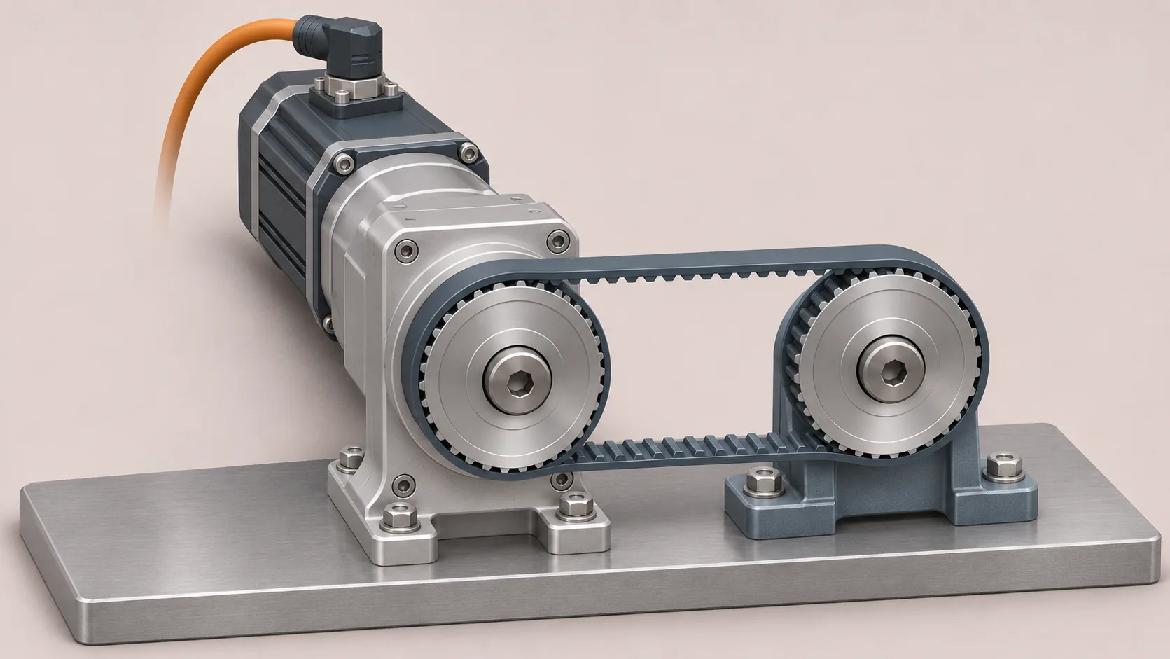
A timing pulley on a gearbox output transmits torque, but it also pulls sideways on the output shaft. That radial load acts on the shaft and its bearings. Checking output torque alone can therefore miss an important part of the gearbox selection.
This example shows why the force that produces torque is different from the load applied to the shaft, and what information is needed to check a real installation. The values are illustrative; they are not measured data or ratings for a particular gearbox.
Why does a belt create radial load?
In a simple two-pulley drive, both belt spans pull on the pulley towards the other pulley. During operation one span generally carries more tension than the other. The difference between those tensions produces the turning moment; the vector sum contributes to the force on the shaft.
The belt's initial tension, operating load, pulley weight and direction of pull all matter. Radial load acts perpendicular to the shaft axis. Axial load acts along it. Check both where the selected arrangement creates both types of force.
Worked example: 15 Nm at a timing pulley
Assume a pulley pitch diameter of 60 mm, so its effective pitch radius is 0.030 m. For illustration, suppose the operating tight-side belt tension is 700 N and the slack-side tension is 200 N.
The effective tangential force is the difference:
F_t = 700 − 200 = 500 N
The transmitted torque at the pulley is:
T = F_t × pitch radius = 500 × 0.030 = 15 Nm
If the two belt-span forces are approximately parallel and pull in the same direction, their combined belt force on the pulley is approximately:
F_radial ≈ 700 + 200 = 900 N
The 500 N force difference and the 900 N approximate shaft load answer different questions. The second value excludes the vector contribution of pulley weight, other attached parts and transient loads. If the spans are not parallel, add the actual forces as vectors instead of simply adding their magnitudes. Use the belt supplier's method and measured or calculated tensions for the real drive.
Where the pulley sits matters
An overhung force creates a bending moment. If an illustrative 900 N resultant acts at a perpendicular distance of 0.050 m from a chosen bearing-support reference, a simple moment estimate at that reference is:
M ≈ F × distance = 900 × 0.050 = 45 Nm
That is a bending moment about the chosen reference, not 45 Nm of transmitted gearbox torque and not a direct substitute for a bearing-life calculation. The actual bearing reactions depend on the internal and external support geometry.
Manufacturers often state permissible radial load at a specified position on the shaft. Check precisely how that position is defined. Do not compare a load at the pulley centre with a catalogue limit at a different location without the manufacturer's correction method.
How to reduce excessive shaft loading
- Position the pulley carefully. Where the drawing and clearance allow, mount its load centre closer to the gearbox output bearing. Keep the required engagement and retaining features.
- Review belt selection and tension. Use the belt supplier's recommended installation and operating values. Do not overtighten a belt as a substitute for design verification.
- Use an independently supported pulley shaft where appropriate. External bearings can carry the belt forces, with a suitable flexible coupling between the supported shaft and gearbox. The coupling and bearing arrangement still require an alignment and load check; adding a bearing to the same rigid shaft does not automatically remove all gearbox load.
- Compare gearbox options. If direct mounting is necessary, request the allowable radial and axial loads at the actual force location for each candidate configuration. A higher torque rating alone does not prove adequate bearing capacity.
The Oriental Motor guide to radial and axial loads discusses how the load position changes permissible force; its support-bearing example illustrates an alternative arrangement.
Check the rest of the drive
Before choosing a gearbox, verify the complete duty cycle: continuous and peak output torque, input speed, starts and reversals, permitted shaft load, service life, temperature, installation orientation and motor interface. Check pulley bore, shaft fit, key or clamping connection and alignment on the actual assembly drawing.
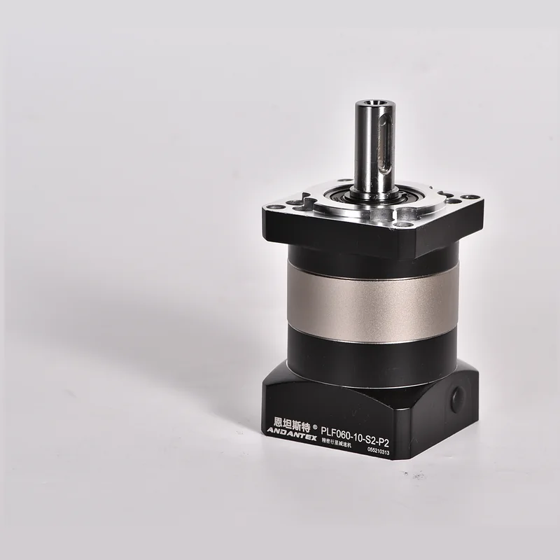
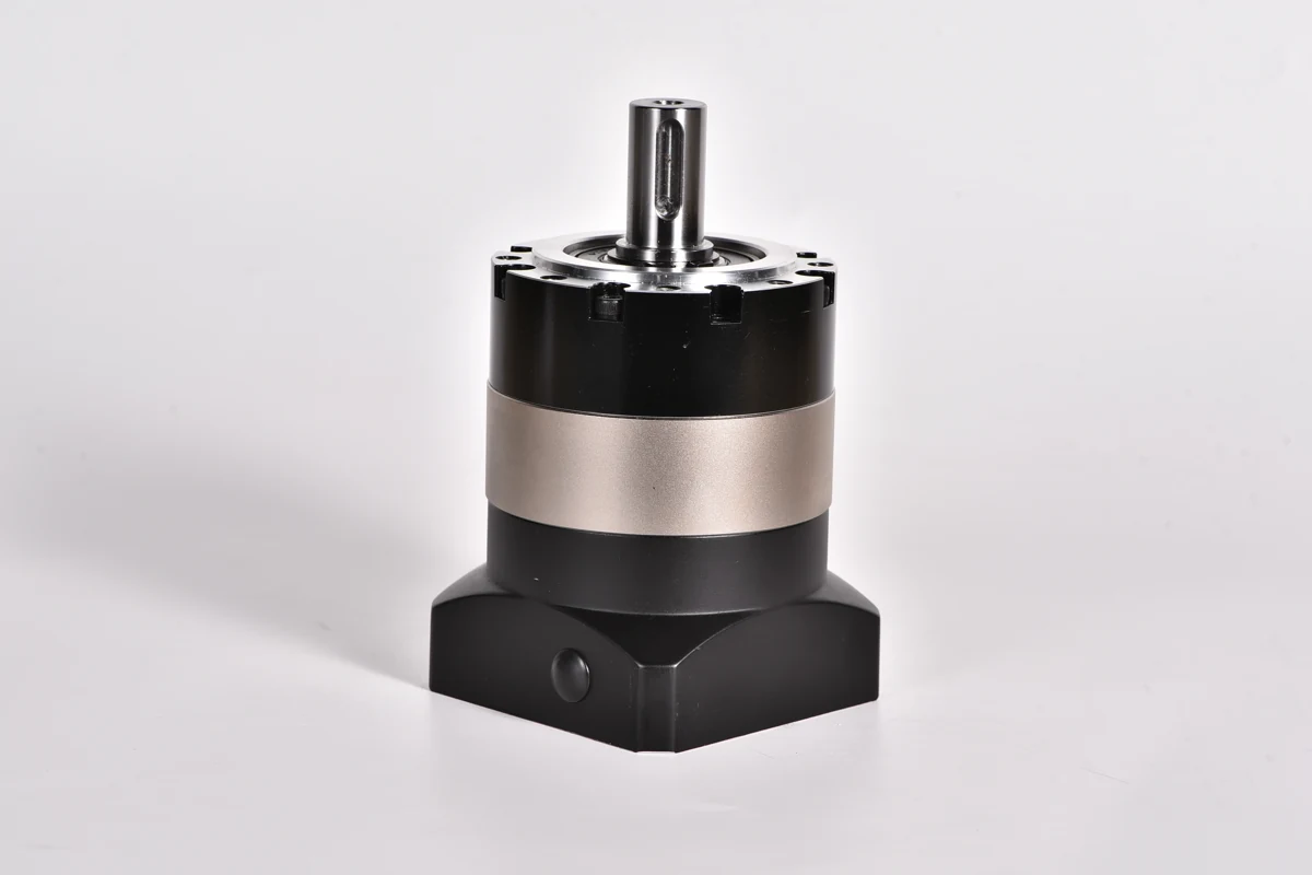
Use the ANDANTEX planetary gearbox torque and speed calculator to estimate transmitted torque and speed, then use the exact model's documentation for allowable loads. For an inline starting point, see PLF060 or PAG060; their suitability depends on the complete application, not the motor power or frame size alone.
What should I send for a review?
Provide the gearbox or motor model, ratio, speed, operating and peak torque, pulley pitch diameter, belt type and tension, distance from the shaft support reference to the pulley centre, pulley mass, mounting orientation and operating cycle. An assembly sketch showing the directions of both belt spans is particularly useful. Send the application details to ANDANTEX for review.
Leave a Technical Question