 PRECISION DRIVE
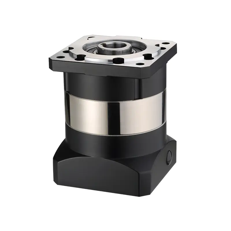
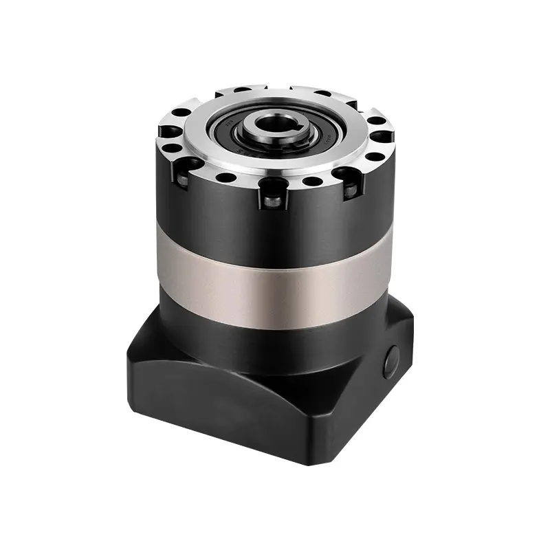
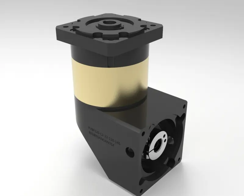
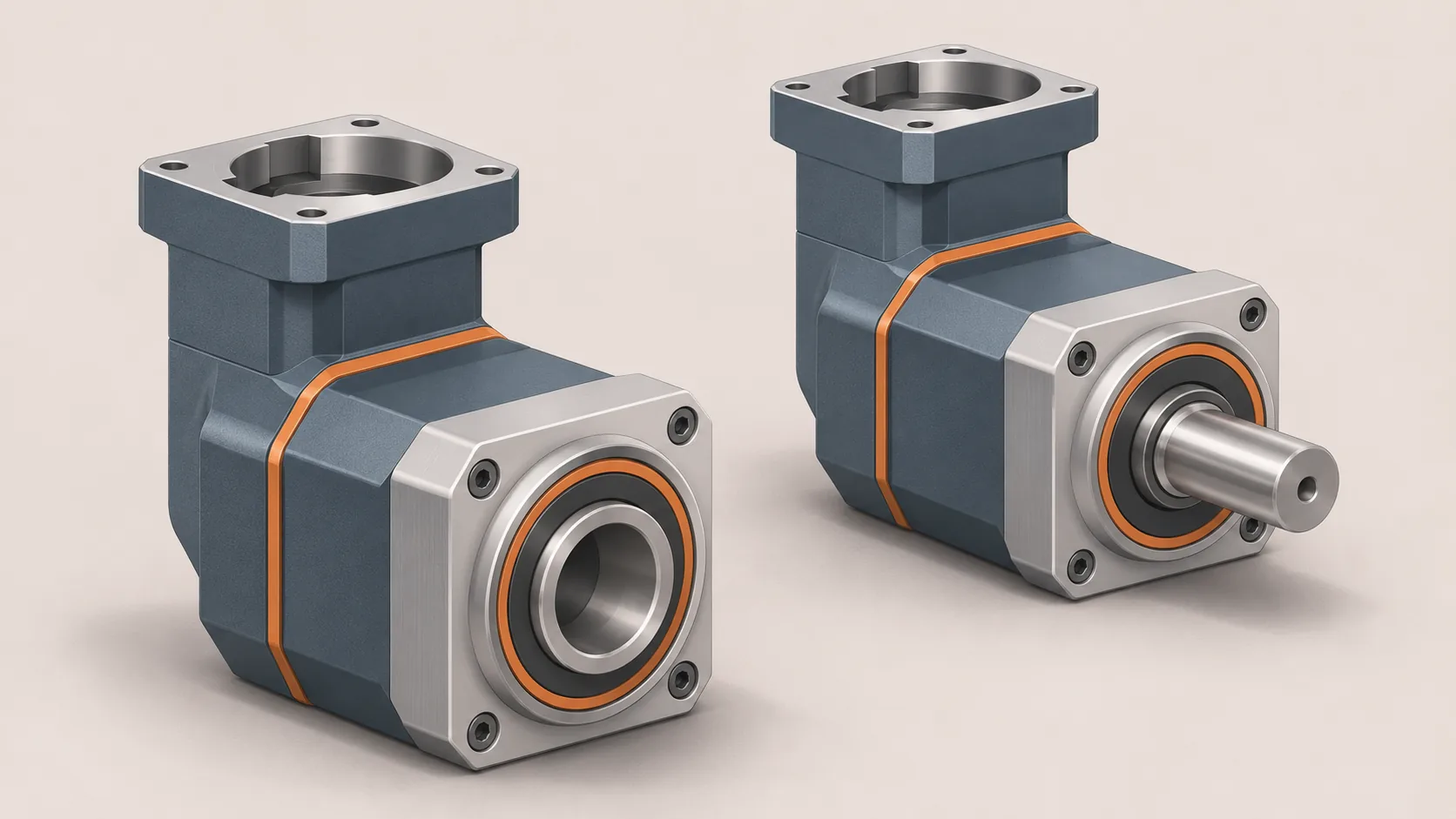
When choosing a right-angle gearbox, the output connection determines how the gearbox fits the machine and how the load reaches its bearings. A hollow output receives a mating machine shaft; a solid output provides a projecting shaft for a coupling, pulley or other connection. The correct choice depends on the complete installation, not on which shape is generally stronger.
This guide explains the practical differences, using conveyor and servo-axis examples. Confirm all dimensions and ratings against the drawing for the exact gearbox configuration.
What is a hollow-shaft gearbox?
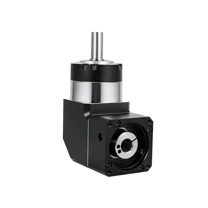
A hollow-output gearbox has a bore in its output member. A machine shaft is inserted into that bore and transmits torque through the specified connection, such as a key, spline or locking device. The gearbox housing must also be restrained in the way specified by its drawing and installation instructions.
Depending on the product, a bore may be available from one side or both sides. A hollow output does not automatically mean an unobstructed through-hole for cables or air lines. The shaft, retaining hardware and internal construction determine what can pass through. Ask for the exact drawing and confirm clearance before routing utilities through the axis.
Hollow-output construction can simplify the connection to an existing machine shaft and reduce the space occupied by separate couplings. It does not remove the need to check alignment, shaft support, torque reaction and removal access.
What is a solid-shaft gearbox?
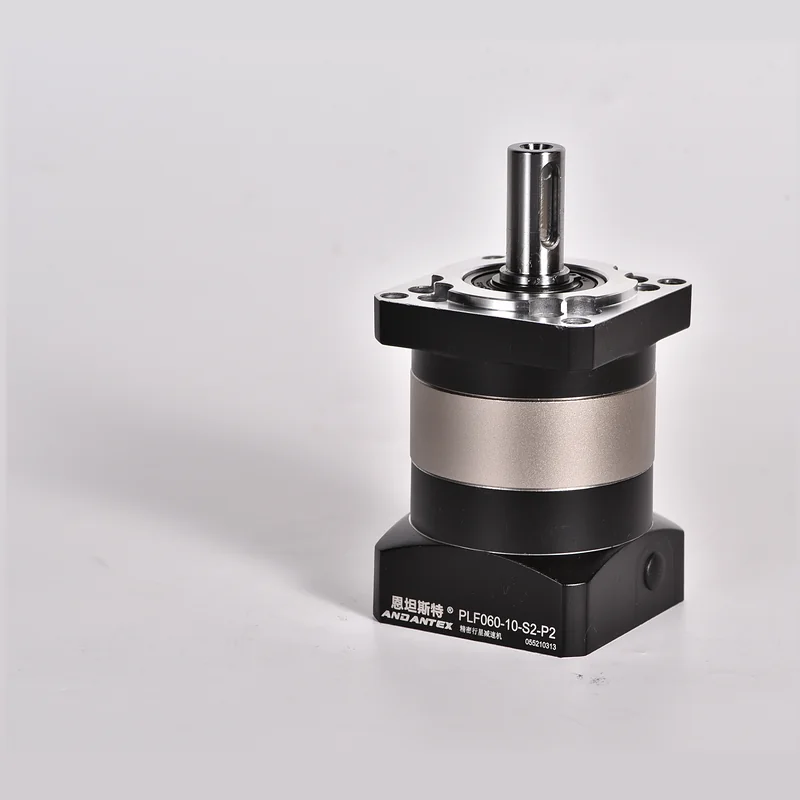
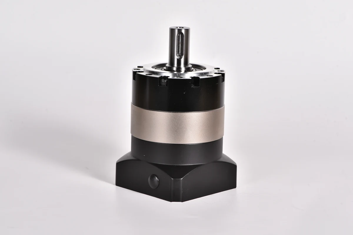
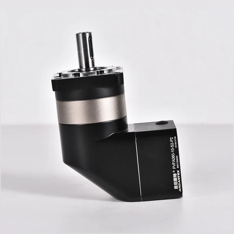
A solid-shaft output projects from the gearbox housing. The machine builder attaches a coupling, timing pulley, chain sprocket or another driven component to that shaft. Depending on the selected configuration, the shaft may be keyed or use another specified connection.
This is useful when the driven machine has a separate input shaft or when a pulley or sprocket must be mounted at the gearbox output. Check the shaft diameter and tolerance, usable length, key and retaining method. Belt or chain tension may also apply significant radial load to the gearbox output bearing.
Compare the installation, not just the output shape
| Check | Hollow output | Solid shaft output |
|---|---|---|
| Connection | Machine shaft fits into the output bore | Coupling, pulley or other component fits onto the projecting shaft |
| First dimensions to confirm | Bore diameter, fit, engagement length and torque connection | Shaft diameter, usable length, tolerance, key and retaining method |
| Support | Verify the machine shaft and gearbox housing support arrangement | Check bearing load from any overhung pulley, sprocket or coupling |
| Service access | Allow for shaft insertion and later removal | Allow room for fitting and removing the output component |
| Precision | Depends on the selected gearbox and complete connection | Depends on the selected gearbox and complete connection |
Neither a hollow nor a solid output is automatically the low-backlash option. Compare the stated backlash for the exact series, ratio and stage, and account for play or compliance in the whole transmission.
Example 1: a conveyor shaft already exists
Suppose a conveyor has a supported drive shaft and limited room at its end. A hollow-output right-angle gearbox may be worth investigating because the shaft can connect directly to the bore. Before ordering, check the shaft diameter and tolerance, key dimensions, engagement length, gearbox torque reaction and whether the shaft bearings and gearbox mounting can carry the actual loads.
If the machine instead needs a timing pulley directly on the reducer, a solid output may offer a straightforward connection. In that case the belt tensions and pulley position create a radial load; check that load as well as output torque. Moving a pulley close to the gearbox bearing can reduce the overhung moment, provided the drawing gives adequate clearance.
Example 2: two output positions
Some machines connect to the output from both sides. Two exposed shafts and two bore openings are different connection layouts; their torque distribution, direction of rotation and allowable load must be confirmed for the particular gearbox. Do not assume that two openings provide independent ratios or that each side can carry the full catalogue torque simultaneously.
ANDANTEX offers several layouts to compare:
- PVFD: single-shaft output.
- PVFH: dual-shaft output.
- PVFG: double-bore output.
- PVFGB: single-bore output.
These names describe output arrangements, not interchangeable dimensions or ratings. Confirm the exact model, reduction ratio and input and output drawings before specifying a replacement.
Five details to send with your enquiry
- Machine and duty: application, running time, starts, reversals and any shock load.
- Motion: required output speed and the available motor speed range.
- Torque and shaft loads: running, acceleration and peak torque, plus radial and axial forces and where they are applied.
- Output connection: shaft or bore diameter and tolerance, key or locking device, engagement length, support and mounting orientation.
- Motor interface and envelope: motor model and drawing, shaft diameter and length, pilot, bolt pattern and available space.
If you have an existing gearbox, share its complete nameplate and dimensioned drawings as well. Send the application details to ANDANTEX for a configuration review.
Frequently asked questions
Is a hollow-output gearbox always smaller?
No. It can eliminate a separate coupling in some layouts, but overall size depends on the housing, shaft support, retaining hardware and removal space.
Can I pass cables through every hollow output?
No. A hollow bore used to receive a driven shaft may be occupied by that shaft or blocked by retaining parts. Check the exact assembly drawing.
Can I replace a single-shaft unit with a double-shaft unit?
Only after comparing the complete interface, direction of rotation, ratio, mounting envelope and allowable loads. Similar frame numbers do not establish interchangeability.
Leave a Technical Question